Types of technical drawings and graphics
Content
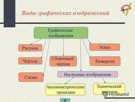
Below are different types of technical drawings depending on their purpose. You'll also find a breakdown of how elements can be represented graphically.
Depending on the purpose, the following types of drawings are distinguished:
composite - shows the relative position, shape and interaction of the individual components of the assembled parts. Knots or parts are numbered and described on a special plate; the dimensions and connection dimensions are also indicated. All fragments of the product must be shown on the drawing. Therefore, axonometric projection and sections are used in assembly drawings;
compilation - an assembly drawing of the product with the applied data and dimensions necessary for the manufacture of individual parts that are part of the presented product;
executive - a drawing of a part containing all the information necessary for its implementation. It allows you to recreate the shape of an object with dimensions. It contains information about the accuracy of manufacturing, the type of material, as well as the necessary projections of the object and the required sections. The executive drawing must be provided with a drawing table, which, in addition to many necessary data, must contain the drawing number and scale size. The drawing number must match the part number on the assembly drawing;
installation – a drawing showing the individual steps and information related to the assembly of the device. Does not contain product dimensions (sometimes overall dimensions are given);
installation - a drawing showing the location of the individual elements of the installation and the way they are connected;
operating room (treatment) - a drawing of a part with the applied data necessary to perform one technological processing;
schematic - a type of technical drawing, the essence of which is to show the principle of operation of a device, installation or system. A drawing of this type carries information not about the size of objects or their spatial relationships, but only about functional and logical relationships. The elements and the relationships between them are represented symbolically;
illustrative - a drawing illustrating only the most essential features of the object;
architectural and construction (technical construction) - a technical drawing depicting a building or its part and serving as the basis for the construction work. This is usually done by a draftsman under the supervision of an architect, architectural technician, or civil engineer and is part of a building project. It usually shows a plan, section or facade of a building or a detail of these drawings. The method of drawing, the amount of detail and the scale of the drawing depend on the stage of the project and its progress. As a rule, the main scale used to represent sections, floor plans and elevations is 1:50 or 1:100, while larger scales are used in the working draft to represent details.
In the process of creating documentation, various ways of graphical representation of objects are used. These include, among others:
See – orthogonal projection showing the visible part of the object and, if necessary, invisible edges;
throw – view in a certain projection plane;
Quadruple room - a graphical representation of the contour of an object located in a certain section plane;
transverse section - a line showing the contour of an object lying on the trace of the section plane, and the contour outside this plane;
scheme - a drawing showing the functions of individual elements and the interdependence between them; elements are marked with appropriate graphic symbols;
outline - the drawing is usually handwritten and not necessarily graduated. Prepared to present the idea of a constructive solution or a draft design of the product, as well as for inventory;
diagram - graphical representation of dependencies using lines on the drawing plane.
MU