Test Drive Internal Friction II

Types of Lubrication and Method of Lubrication of Various Engine Parts
Lubrication types
The interactions of moving surfaces, including friction, lubrication and wear, are the result of a science called tribology, and when it comes to the types of friction associated with internal combustion engines, designers define several types of lubricant. Hydrodynamic lubrication is the most demanded form of this process, and the typical place where it occurs is in the main and connecting rod bearings of the crankshaft, which are subjected to much higher loads. It appears in the miniature space between the bearing and the V-shaft, and is brought there by an oil pump. The moving surface of the bearing then acts as its own pump, which pumps and distributes the oil further and ultimately creates a sufficiently thick film throughout the entire bearing space. For this reason, designers use sleeve bearings for these engine components, since the minimum contact area of the ball bearing creates an extremely high load on the oil layer. Moreover, the pressure in this oil film can be almost fifty times higher than the pressure generated by the pump itself! In practice, the forces in these parts are transmitted through the oil layer. Of course, in order to maintain the hydrodynamic lubrication state, it is necessary that the engine lubrication system always provides a sufficient amount of oil.
It is possible that at some point, under the influence of high pressure in certain parts, the lubricating film becomes more stable and harder than the metal parts that it lubricates, and even leads to deformation of metal surfaces. Developers call this type of lubrication elastohydrodynamic, and it can manifest itself in the ball bearings mentioned above, in gear wheels or in valve lifters. In the event that the speed of the moving parts relative to each other becomes very low, the load increases significantly or there is not enough oil supply, so-called boundary lubrication often occurs. In this case, lubrication depends on the adhesion of the oil molecules to the supporting surfaces, so that they are separated by a relatively thin but still accessible oil film. Unfortunately, in these cases there is always a danger that the thin film will be "punctured" by sharp parts of irregularities, therefore, appropriate antiwear additives are added to the oils, which cover the metal for a long time and prevent its destruction by direct contact. Hydrostatic lubrication occurs in the form of a thin film when the load changes direction abruptly and the speed of the moving parts is very low. It is worth noting here that bearing companies such as main connecting rods such as Federal-Mogul have developed new technologies to coat them so that they can solve problems with start-stop systems such as bearing wear on frequent starts, partially dry that they are subjected to with each new launch. This will be discussed later. This frequent start-up, in turn, leads to a transition from one form of lubricant to another and is defined as “mixed film lubricant”.
Lubrication systems
The earliest automotive and motorcycle internal combustion engines, and even later designs, had drip "lubrication" in which oil entered the engine from a kind of "automatic" grease nipple by gravity and flowed through or burned out after passing through it. Designers today define these lubrication systems, as well as lubrication systems for two-stroke engines, in which oil is mixed with fuel, as "total loss lubrication systems." Later, these systems were improved with the addition of an oil pump to supply oil to the inside of the engine and to the (often found) valve train. However, these pumping systems have nothing to do with the later forced lubrication technologies that are still in use today. The pumps were installed externally, feeding oil into the crankcase, and then it reached the friction parts by splashing. Special blades at the bottom of the connecting rods sprayed oil into the crankcase and cylinder block, as a result of which excess oil was collected in mini-baths and channels and, under the action of gravity, flowed into the main and connecting rod bearings and camshaft bearings. A kind of transition to systems with forced lubrication under pressure is the Ford Model T engine, in which the flywheel had something like a water mill wheel, which was intended to lift oil and pipe it to the crankcase (and note the transmission), then the lower parts crankshaft and connecting rods scraped oil and created an oil bath for rubbing parts. This was not particularly difficult given that the camshaft was also in the crankcase and the valves were stationary. The First World War and aircraft engines that simply did not work with this kind of lubricant gave a strong push in this direction. This was how systems were born that used internal pumps and mixed pressure and spray lubrication, which were then applied to new and heavier loaded automobile engines.
The main component of this system was an engine driven oil pump that pumped oil under pressure only to the main bearings, while other parts relied on spray lubrication. Thus, it was not necessary to form grooves in the crankshaft, which are necessary for systems with fully forced lubrication. The latter arose as a necessity with the development of engines that increase speed and load. This also meant that the bearings had to be not only lubricated but also cooled.
In these systems, pressurized oil is supplied to the main and lower connecting rod bearings (the latter receives oil through grooves in the crankshaft) and camshaft bearings. The great advantage of these systems is that oil practically circulates through these bearings, i.e. passes through them and enters the crankcase. Thus, the system provides much more oil than is necessary for lubrication, and therefore they are intensively cooled. For example, back in the 60s, Harry Ricardo first introduced a rule that provided for the circulation of three liters of oil per hour, that is, for a 3 hp engine. – XNUMX liters of oil circulation per minute. Today's bicycles are replicated many times more.
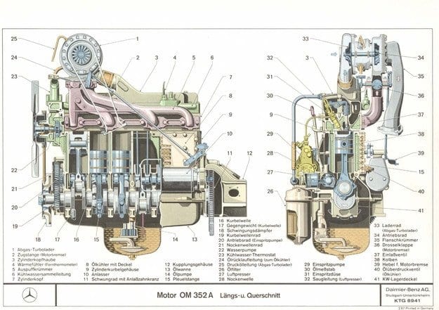
The circulation of oil in the lubrication system includes a network of channels built into the body and engine mechanism, the complexity of which depends on the number and location of cylinders and the timing mechanism. For the sake of reliability and durability of the engine, designers have long favored channel-shaped channels instead of pipelines.
An engine-driven pump draws oil from the crankcase and directs it to an in-line filter mounted outside the housing. It then takes one (for in-line) or a pair of channels (for boxer or V-shaped engines), extending almost the entire length of the engine. Then, using small transverse grooves, it is directed to the main bearings, entering them through the inlet in the upper bearing shell. Through a peripheral slot in the bearing, part of the oil is evenly distributed in the bearing for cooling and lubrication, while the other part is directed to the lower connecting rod bearing through an oblique bore in the crankshaft connected to the same slot. Lubricating the upper connecting rod bearing is more difficult in practice, so the upper part of the connecting rod is often a reservoir designed to contain oil splashes under the piston. In some systems, oil reaches the bearing through a bore in the connecting rod itself. The piston bolt bearings are, in turn, splash lubricated.
Similar to the circulatory system
When a camshaft or chain drive is installed in the crankcase, this drive is lubricated with straight-through oil, and when the shaft is installed in the head, the drive chain is lubricated by controlled oil leakage from the hydraulic extension system. In the Ford 1.0 Ecoboost engine, the camshaft drive belt is also lubricated - in this case by immersion in the oil pan. The way lubricating oil is supplied to the camshaft bearings depends on whether the engine has a bottom or top shaft - the former usually receives it grooved from the crankshaft main bearings and the latter grooved connected to the main lower groove. or indirectly, with a separate common channel in the head or in the camshaft itself, and if there are two shafts, this is multiplied by two.
Designers seek to create systems in which valves are lubricated at precisely controlled flow rates to avoid flooding and oil leakage through the valve guides in the cylinders. Additional complexity is added by the presence of hydraulic lifts. Rocks, irregularities are lubricated in an oil bath or by spraying in miniature baths, or by means of channels through which oil leaves the main channel.
As for the cylindrical walls and piston skirts, they are completely or partially lubricated with oil coming out and spreading in the crankcase from the lower connecting rod bearings. Shorter engines are designed so that their cylinders get more oil from this source because they have a larger diameter and are closer to the crankshaft. In some engines, the cylinder walls draw additional oil from a side hole in the connecting rod housing, which is usually directed towards the side where the piston exerts more lateral pressure on the cylinder (that which the piston exerts pressure on during combustion during operation). ... In V-engines, it is common to inject oil from a connecting rod moving into the opposite cylinder onto the cylinder walls so that the top side is lubricated, and then it is pulled to the bottom side. It is worth noting here that in the case of turbocharged engines, oil enters the bearing of the latter through the main oil channel and pipeline. However, they often use a second channel that directs the oil flow to special nozzles directed at the pistons, which are designed to cool them. In these cases, the oil pump is much more powerful.
In dry sump systems, the oil pump receives oil from a separate oil tank and distributes it in the same way. The auxiliary pump sucks the oil / air mixture from the crankcase (so it must have a large capacity), which passes through the device to separate the latter and return it to the reservoir.
The lubrication system may also include a radiator to cool the oil in heavier engines (this was common practice for older engines using simple mineral oils) or a heat exchanger connected to the cooling system. This will be discussed later.
Oil pumps and relief valves
Oil pumps, including a gear pair, are extremely suitable for the operation of an oil system and are therefore widely used in lubrication systems and in most cases are driven directly from the crankshaft. Another option is rotary pumps. Recently, sliding vane pumps have also been used, including variable displacement versions, which optimize the operation and thus their performance in relation to speed and reduce energy consumption.
Oil systems require relief valves because at high speeds the increase in the amount supplied by the pump does not match the amount that can pass through the bearings. This is due to the fact that in these cases, strong centrifugal forces are formed in the bearing oil, preventing the supply of a new amount of oil to the bearing. In addition, starting the engine at low outside temperatures increases oil resistance with an increase in viscosity and a decrease in backlash in mechanisms, which often leads to critical values of oil pressure. Most sports cars use an oil pressure sensor and an oil temperature sensor.
(to follow)
Text: Georgy Kolev

