Junkers Ju 87 D i G cz.4
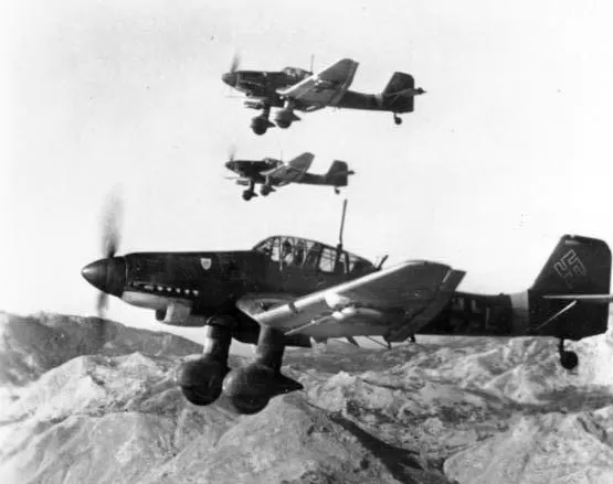
Junkers Ju 87 G-1 anti-tank fighter preparing for takeoff.
The experience gained by the crews of dive bombers during the fighting in Spain and in the Polish campaign of 1939 confirmed the need to modernize the Ju 87 aircraft. Small arms. The most important conditions for improving performance were a new engine of greater power and a change in the aerodynamics of the airframe.
Work on a new version of the "Stukka" began in the spring of 1940, and already in May the design received the official designation Junkers Ju 87 D. Replacing the power unit. The Jumo 211 J-12 211-cylinder liquid-cooled in-line engine with a maximum power of 1 hp proved to be an ideal alternative. The new engine was longer than the one used in the Ju 1420 B version by more than 87 cm, so its casing had to be lengthened and reshaped. At the same time, a new cooling system was developed. The oil cooler was moved under the lower part of the engine casing, and under the wings, at the trailing edge of the center section, two liquid radiators were installed. Another change was the new cockpit cover previously tested on the Ju 40 B, W.Nr. 87.
The new Jumo 211 J-1 engine was first installed in the Ju 87 B-1, W.Nr. 0321, D-IGDK in October 1940. Tests that lasted several weeks were interrupted by continuous failures of an unfinished power unit.
The first official prototype of the Ju 87 D was the Ju 87 V21, W.Nr. 0536, D-INRF, completed March 1941. Jumo 211 J-1 powered aircraft tested from March to August 1941 at the Dessau factory. In August 1941, the Jumo 211 J-1 engine was replaced by the Jumo 211 F. Immediately at the start of testing with the new power plant, the propeller came off while operating at 1420 rpm. On September 30, 1939, the repair of the aircraft was completed and it was transferred to the Erprobungsstelle Rechlin. After a series of flight tests, on 16 October 1941 the aircraft was officially handed over to the Luftwaffe. The car was later used to test the engine and cooling system. In February 1942, the aircraft returned to Dessau, where new radiator covers were installed on it, and on September 14, 1943, the prototype was handed over to the front.
Second prototype, Ju 87 V22, W.Nr. 0540, SF+TY, was due to be completed on schedule in late 1940, however engine problems delayed completion and it was not until May 1941 that flight testing began. November 10, 1941 the aircraft was transferred to the Luftwaffe. The results of the tests carried out satisfied both the Junkers plant and representatives of the Rekhlin Experimental Center. The early frosts of November 1941 also made it possible to carry out cold start tests, it turned out that starting the engine even at very low temperatures does not require special work and does not cause failure of the power unit.
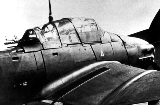
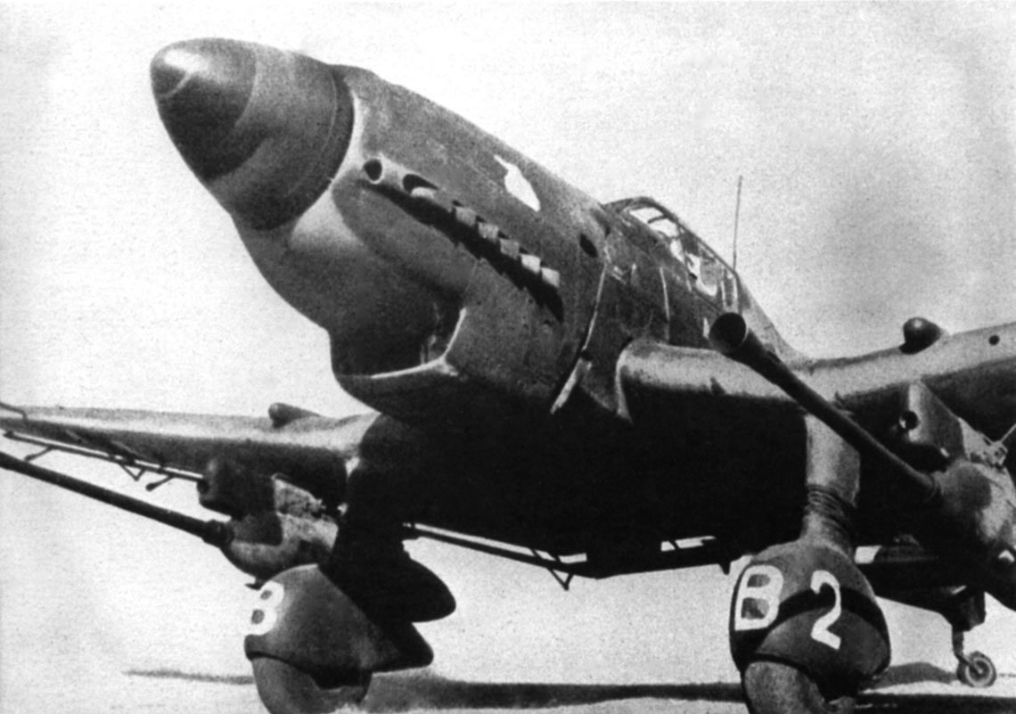
Junkers Ju 87 D-1, W.Nr. 2302 tested with additional armor.
In early 1942, the prototype returned to Dessau, where stability tests and minor modifications to the Jumo 211 J-1 engine were carried out, after which the aircraft was sent back to Rechlin. On August 20, 1942, during one of the test flights, the plane crashed into Lake Müritzsee. His crew, pilot: Fw. Herman Ruthard, a civilian worker at the experimental center, has died. The cause of the accident was probably the loss of consciousness by the pilot as a result of carbon dioxide poisoning.
Third prototype Ju 87 V23, W.Nr. 0542, PB+UB, completed in April 1941, transferred to Erprobungsstelle Rechlin a month later. It was a sample for the Ju 87 D-1 version. Problems with the delivery of the Jumo 211 J-1 engine stopped another Ju 87 V24 prototype, W.Nr. 0544, BK+EE, which was not completed until August 1941. The aircraft was transferred to Rechlin, where it soon broke down and returned to Dessau with a damaged fuselage. After repairs in November 1941, it was again transported to Rechlin. After the end of the tests, the car was placed in the front.
Fifth prototype, Ju 87 V25, W.Nr. 0530, BK+EF, was standard for the tropical version of the Ju 87 D-1/trop. The airframe was completed in early March 1941, but only in July 1941 was the Jumo 211 J-1 engine installed. In the summer, the car was tested and on September 12, 1941 was transported to Rechlin, where it was tested with a Delbag dust filter.
The decision to mass-produce the Ju 87 D-1 was made in 1940, when an order was placed for the production of 495 copies of this aircraft. They were to be delivered between May 1941 and March 1942. In early February 1942, the Technical Department of the Imperial Air Ministry increased the order to 832 Ju 87 D-1s. All machines were to be manufactured at the Weser plant. Problems with the Jumo 211 J engines led to a delay in the order. The first two series of aircraft were to be completed in June 1941, but Karman was unable to prepare the upper fuselage components in time. The first production aircraft was assembled only on June 30, 1941. Despite the delay, the Reich Air Ministry believed that 1941 Ju 48 D-87s would roll off the Weser assembly lines in July 1. Meanwhile, in July 1941, only the first copy was built; it was destroyed in the factory. Representatives of the RLM and the management of the Junkers plant, which issued the license for the construction of the Ju 87 D-1 to the Weser plant, hoped that by the end of September 1941 the delay in mass production would be compensated. However, further difficulties dashed these hopes. Also in August 1941, not a single Ju 87 D-1 left the assembly shop of the Bremen plant. Only in September, the Weser factories handed over to the Luftwaffe the first two production aircraft that entered the test centers.
In October-November 1941, a total of 61 Ju 87 D-1s were assembled, which, due to the terrible weather conditions at that time in Lemwerder, did not fly until December, and then were transferred to parts of the front.
Technical description Ju 87 D-1
The Junkers Ju 87 D-1 was a two-seat, single-engine, all-metal low-wing aircraft with a classic fixed landing gear. The fuselage of the aircraft had an oval section with a semi-sheathed structure made entirely of metal. The body was divided into halves, permanently connected with rivets. The working cover made of smooth duralumin was fastened with convex rivets with spherical heads in places of increased loads and smooth rivets in places of lesser loads.
The hull structure consisted of 16 frames connected by perpendicular stringers, and four crossbars located in its front part, reaching up to 7 frames inclusive. The #1 full-length frame was also the engine firewall. In front of the fuselage, additional auxiliary frames were built to strengthen the hull, they also served as supports for the bomb boom.
The cockpit, located in the middle part of the fuselage between the 2nd and 6th frames, was covered with a richly glazed four-part cover made of laminated or organic glass, providing good visibility from all sides. Sliding elements of the cab lining are equipped with locks for their emergency unlocking. In the middle of the cabin, an anti-tilting overpass was mounted, connected to an armored partition. The windshield was equipped with bulletproof glass 25 mm thick. Additional shelter for the pilot was an armored metal seat with a thickness of 4 to 8 mm, as well as an armor plate 10 mm thick behind his head and armor plates 5 mm thick installed in the cabin floor.
The radio operator was protected by two armor plates, the first of which, 5 mm thick, was built into the floor, the second, profiled in the form of a frame, was placed between frames 5 and 6. An armored GSL-K 81 with a MG 81 Z machine gun served as an additional cover. There was a small window in the pilot's floor with a metal curtain that made it easier to observe the ground before diving into the plane. Behind frame number 8 was a metal container, accessible only from the outside, in which there was a first-aid kit.
The all-metal three-sided double-spar airfoil featured a distinctive flattened W-shape that was created by attaching positive-lift outer parts to a negative-lift center section. The outlines of the blades are trapezoid with rounded ends. The center section was integrally connected to the fuselage. Two liquid coolers were built under the center section. The outer parts of the airfoil were attached to the center section with four ball joints designed by Junkers. The working cover is made of smooth duralumin sheet. Below the trailing edge, in addition to the main wing profile, there are two-section flaps, separate for the center section and the ending. Flaps and one-piece ailerons equipped with trimmers were mounted on special rods patented by Junkers.
The ailerons had a mechanical drive, and the flaps had a hydraulic drive. All movable surfaces of the wings were covered with a smooth duralumin sheet. The flap and aileron system according to the Junkers patent was called the Doppelflügel, or double wing. The gaps between the profile and its moving parts ensured greater efficiency, and the entire system was technologically simple. Under the wings, at the first spar, there were automatically controlled slotted air brakes, which helped to bring the car out of a dive flight.
The tail section, which has an all-metal structure, was sheathed with a smooth duralumin sheet. The vertical stabilizer had a trapezoidal shape, the rudder was driven by steel cables. An adjustable horizontal stabilizer, without lifting, with a rectangular contour, was supported by fork-shaped posts made of steel pipes profiled with duralumin sheet. The height adjusters were driven by pushers. Both the elevator and rudder were massively and aerodynamically balanced, with trim tabs and raised ridges.
The classic free-standing fixed landing gear with a tailwheel provided good ground stability. One main landing gear was mounted in knots on spars No. 1 at the junction of the center section with the extreme parts of the wings. KPZ struts manufactured by Kronprinz, ending in a fork encircling the wheel, had spring damping with oil damping. The main landing gear was profiled with fairings made of smooth duralumin of a characteristic shape, which is one of the distinguishing features of the Stuka aircraft. The wheels were equipped with medium pressure tires measuring 840 x 300 mm. The recommended tire pressure was to be 0,25 MPa. The braking system consisted of hydraulic drum brakes. The fluid was used for the brake system.
brake fl-Drukel. The fixed tail wheel, mounted on the Kronprinz shin fork, had spring damping and was attached to a horizontal frame located between vertical ribs No. 15 and 16. The tail wheel shank was embedded in a special box, providing 360 ° rotation. A tire with dimensions of 380 x 150 mm was installed on the rim with a recommended pressure of 3 to 3,5 atm. During takeoff, flight and landing, the tail wheel could be locked in position with a cable controlled from the cockpit. After every 500 flights, a general technical inspection of the landing gear was recommended. Built-in emergency skid to protect the rear of the fuselage in the event of a forced landing.