Rear axle MAZ
Content
Repair of the MAZ rear axle consists in replacing worn or damaged parts. The design of the rear axle allows most repairs to be carried out without removing it from the vehicle.
To replace the drive gear oil seal, you must:
- disconnect the cardan shaft from flange 14 (see Fig. 72) of the gear shaft;
- unscrew and unscrew nut 15, remove flange 14 and washer 16;
- unscrew the nuts securing the stuffing box cover 13 and use the dismantling bolts to remove the stuffing box cover;
- replace the stuffing box, filling its internal cavities with grease 1-13, and assemble the assembly in the reverse order of disassembly (the stuffing box is pressed flush with the outer end of the cover).
If it is necessary to replace the stuffing box 9 (see Fig. 71), the axle shaft must:
- drain the oil from the crankcase of the bridge by unscrewing the drain and filler plugs;
- disconnect the cardan shaft;
- remove small covers 7 (see Fig. 73) of wheel gears;
- unscrew the large cap fixing bolt 15 and, screwing it into the threaded holes at the ends of the axle shafts 22, carefully remove it together with the sun gears 11 from the wheel gears;
- unscrew the nuts from the studs securing the central gearbox to the axle box (except for the top two). After that, using a trolley with a lift, remove the gearbox, screw two removable bolts into the gearbox flange to the axle housing, and after removing the remaining two upper nuts, replace the axle gearbox oil seal with a puller, filling the inner cavity with grease 1-13.
The rear axle is assembled in the reverse order, and the axle shafts must be installed carefully, turning them to avoid twisting the sealing lip.
Usually bridge repair is associated with the removal and disassembly of the central gearbox or wheel drive.
Disassembly of the central gearbox MAZ
Before removing the central gearbox, it is necessary to drain the oil from the axle housing, disconnect the cardan shaft and release the parking brake. Then remove the small wheel gear covers, unscrew the large wheel gear cover bolt and, turning it alternately in the threaded bushings at the ends of the axle shafts, remove the axle shafts from the differential. Loosen the studs that secure the central gearbox to the axle housing and remove the gearbox using a dolly.
The central gearbox is most conveniently disassembled on a swivel mount. In the absence of support, a low workbench with a height of 500-600 mm can be used.
The sequence for disassembling the gearbox is as follows:
- remove the drive gear 20 (see Fig. 72) complete with bearings;
- unscrew nuts 29 and 3 from differential covers;
- remove differential bearing caps 1;
- unscrew the nuts from the studs of the differential cups and open the differential (remove the satellites, side gears, thrust washers).
Wash the folding parts of the central gearbox and inspect carefully. Check the condition of the bearings, on the working surfaces of which there should be no spalling, cracks, dents, peeling, as well as destruction or damage to the rollers and separators.
When inspecting the gears, pay attention to the absence of chips and breakages of the teeth, cracks, chips of the cement layer on the surface of the teeth.
With increased noise of the gears of the central gearbox during operation, the value of the side clearance of 0,8 mm can serve as a basis for replacing a pair of bevel gears.
If necessary, replace the driving and driven bevel gears as a set, as they are matched at the factory in pairs for contact and side clearance and have the same marking.
When inspecting the parts of the differential, pay attention to the condition of the surface of the necks of the crosses, holes and spherical surfaces of the satellites, the bearing surfaces of the side gears, bearing washers and the end surfaces of the differential cups, which must be free of burrs.
In case of significant wear or loose fit, replace the satellite bushing. A fresh bushing is processed after being pressed into the satellite to a diameter of 26 ^ + 0,045 mm.
With significant wear of the bronze bearing washers of the axle shafts, they must be replaced. The thickness of the new bronze washers is 1,5 mm. After assembling the differential, it is recommended to measure the gap between the side gear and the supporting bronze washer, which should be between 0,5 and 1,3 mm. The gap is measured with a feeler gauge through the window in the differential cups, when the satellites run into the support washers to failure, and the side gear is pressed against the satellites, that is, it engages with them without play. Differential cups are replaced as a set.
Assemble the central gearbox in the following sequence:
- assemble the drive gear, install it in the bearing housing and adjust the tapered bearings with preload;
- assemble the differential, install it in the crankcase and adjust the differential bearings with preload;
- install the drive gear in the gearbox housing;
- adjust the engagement of the bevel gears;
- screw the driven gear limiter into the gear until it stops, and then loosen it by 1/10-1/13 of a turn, which corresponds to a gap between them of 0,15-0,2 mm, and tighten the lock nut.
Disassembly of the wheel drive and removal of the rear wheel hub
The disassembly sequence is as follows:
- loosen the nuts on the rear wheels;
- place a jack under one side of the rear axle beam and
- hang the bucket with wheels, then put it on a support and remove the jack;
- unscrew the nuts holding the rear wheels, remove the clamps and the outer wheel, spacer ring and inner wheel;
- drain the oil from the wheel gear;
- remove the large cover 14 (see Fig. 73) from the wheel drive assembly with the small cover 7;
- remove the driven gear 1, for which use two bolts from the large cover as a puller;
- screw the bolt of the large cover into the threaded hole of the half shaft 22, remove the half shaft with the central gear 11 as a whole;
- unscrew the locking bolts of the 3 axles from the satellites, install the puller and remove the axles of the 5 satellites, then remove the satellites complete with bearings;
- unscrew the lock nut 27 from the hub bearings, remove the retaining ring 26, unscrew the nut 25 from the bearings and remove the inner cup 21 from the carrier;
- remove the bearing spacer, install the hub puller and remove the hub assembly with the brake drum.
When replacing the oil seal and hub bearing, you must:
- unscrew the brake drum mounting bolts and remove the dust collector and stuffing box cover;
- remove the stuffing box from the cover and install a new stuffing box with light blows of a hammer;
- Using a puller, pull out the outer and inner races of the wheel bearing.
Rinse the hub and wheel gear parts and inspect them carefully.
Chipping of the carburizing layer on the surface of the gear teeth is not allowed. If there are cracks or broken teeth, the gears should be replaced.
Installation of a nave and installation of a drive of a wheel is made upside-down. In this case, it must be taken into account that the double tapered inner bearing is manufactured with a guaranteed preload, which is ensured by the installation of a spacer ring. In this assembly, the bearing is marked at the ends of the cages and on the outer surface of the spacer ring. This bearing should only be installed as a complete set in accordance with the brand.
Replacement of individual parts of the kit is not allowed, as this changes the axial clearance of the bearing, which leads to its destruction.
The hub bearings are not adjustable, however proper hub alignment is ensured by tightening the inner races of these bearings with a nut and locknut. The force required to tighten the hub bearing nut should be approximately equal to 80-100 kg on a wrench with a 500 mm box wrench.
Maintenance of the rear axle MAZ
Maintenance of the rear axle consists in checking and maintaining the required level of lubrication in the intermediate gearbox and wheel gears, timely changing the lubricant, cleaning the ventilation holes, checking and tightening the fasteners, checking the operation noise and the rear axle heating temperature.
When servicing the rear axle, special attention should be paid to adjusting the central gearbox. Adjustment is made with the gearbox removed; In this case, the tapered bearings of the driving bevel gear and the differential bearings are first adjusted, and then the bevel gears along the contact patch.
To adjust the bearings of the drive bevel gear, you must:
- disassemble the parking brake and remove the caliper cover 9 (see Fig. 72);
- drain the oil;
- unscrew the nuts on the studs of the drive gear bearing housing and using removable bolts 27 remove the housing 9 with the drive bevel gear assembly;
- fixing the crankcase 9 in a vice, determine the axial clearance of the bearings using an indicator;
- having released the crankcase 9, clamp the driving bevel gear in a vise (place soft metal pads in the jaws of the vise). Loosen and unscrew flange nut 15, remove washer and flange. Remove the cover with removable screws. Remove the oil deflector 12, the inner ring of the front bearing and the adjusting washer 11;
- measure the thickness of the adjusting washer and calculate to what value it is necessary to reduce it to eliminate the axial clearance and obtain a preload (the decrease in the thickness of the washer should be equal to the sum of the measured axial shaft clearances in terms of the indicator and the preload value of 0,03-0,05 mm);
- grind the adjusting washer to the required value, install it and other parts, except for the cover 13 with the stuffing box, which should not be installed, since the friction of the stuffing box against the neck of the flange will not allow adjustment to accurately measure the moment of resistance when turning the gear in the bearings. When tightening the collar nut, turn the bearing housing so that the rollers are correctly positioned in the bearing races;
- check the preload of the bearings according to the magnitude of the moment required to rotate the drive gear, which should be equal to 0,1-0,3 kgm. This moment can be determined using a torque wrench on nut 15 or by measuring the force applied to the hole in the flange for the propeller shaft mounting bolts (Fig. 75). The force applied perpendicular to the radius of the holes in the flange should be between 1,3 and 3,9 kg. Be aware that too much preload in tapered roller bearings will cause them to heat up and wear out quickly. With normal bearing preload, remove the nut from the pinion shaft, observing its position, and the flange, then reinstall cover 13 (see Fig. 72) with the gland and finally assemble the assembly.
The tightening of the differential bearings is adjusted using nuts 3 and 29, which must be screwed in to the same depth so as not to disturb the position of the gear until the required preload is obtained in the bearings.
The bearing preload is determined by the amount of torque required to rotate the differential, which should be in the range of 0,2-0,3 kgm (without bevel gear). This moment is determined by a torque wrench or by measuring the force applied to the radius of the differential cups, and is equal to 2,3-3,5 kg.
Rice. 75. Checking the tightness of the bearing of the drive gear shaft of the central gearbox
The procedure for checking and adjusting the bevel gear engagement is as follows:
- before installing the crankcase, 9 bearings with the drive gear into the gearbox housing, dry the teeth of the bevel gears and grease three or four teeth of the drive gear with a thin layer of paint over their entire surface;
- install the crankcase 9 with the drive gear into the gearbox crankcase; screw the nuts onto the four crossed studs and turn the drive gear behind the flange 14 (to one side and the other);
- according to the traces (contact points) obtained on the teeth of the driven gear (Table 7), the correct engagement of the gears and the nature of the gear adjustment are established. Gear engagement is regulated by changing the number of spacers 18 under the flange of the drive gear bearing housing and nuts 3 and 29, without disturbing the adjustment of the differential bearings. To move the drive gear away from the driven gear, it is necessary to place additional shims under the crankcase flange, and, if necessary, to bring the gears together, remove the shims.
Nuts 3 and 29 are used to move the driven gear. In order not to disturb the adjustment of bearings 30 of the differential, it is necessary to tighten (unscrew) nuts 3 and 29 at the same angle.
When adjusting the clutch (along the contact patch) on the gear teeth, the lateral gap between the teeth is maintained, the value of which for a new pair of gears should be within 0,2-0,5 microns. Reducing the lateral clearance between the gear teeth by shifting the contact patch from the recommended position is not allowed, as this leads to a violation of the correct engagement of the gears and their rapid wear.
After adjusting the gear engagement, tighten all the studs securing the bearing housing to the gearbox housing, set the stops on the bearing nuts, tighten the limiter 25 until a minimum clearance of 0 0,15-0,2 mm is obtained between the cracker and the driven gear (the minimum gap is set by rotating the gears of the driven gear per turn). After that, lock the driven gear limiter 25 with a lock nut.
When removing the central gearbox from the car (for adjustment or repair), check the gap between the end plane of the side gearbox and the support washer, set at the factory within 0,5-1,3 mm.
The gap is checked with a feeler gauge through the windows in the differential cups, when the satellites run into the support washers to failure, and the side gear is pressed against the satellites, that is, it engages with them without play.
Possible malfunctions of the rear axle and ways to eliminate them are shown in table eight.
| The position of the contact patch on the driven gear | How to get the right gear | |
| Back and forth | ||
| Correct bevel gear contact | ||
| Move the driven gear to the drive gear. If this results in too little gear tooth gap, move the drive gear away from the driven gear. | ||
| Move the driven gear away from the drive gear. If this results in excessive gear tooth play, move the drive gear to the driven position. | ||
| Move the driven gear to the drive gear. If at the same time it is necessary to change the backlash in the hitch, transfer the drive gear to the driven gear | ||
| Move the driven gear away from the drive gear. If this requires changing the side clearance in the clutch, move the drive gear away from the driven gear. | ||
| Move the drive gear towards the driven gear. If the clearance in the clutch is too small, move the driven gear away from the drive gear. | ||
| Move the drive gear away from the driven gear. If there is too much play, move the driven gear towards the drive gear. |
Read also Specifications of the ZIL-131 winch
| Cause of failure | Resource |
| Bridge heating increase | |
| Too much or too little oil in the crankcase | Check and top up the oil level in the crankcase |
| Incorrect gear shifting | Adjust gearing |
| Increased bearing preload | Adjust bearing tension |
| Increased bridge noise | |
| Violation of the fit and engagement of bevel gears | Adjust bevel gear |
| Worn or misaligned tapered bearings | Check the condition of the bearings, if necessary, replace them and adjust the tightness |
| Severe gear wear | Replace worn gears and adjust transmission |
| Increased noise of the road bridge in the turn | |
| Differential Faults | Disassemble the differential and troubleshoot |
| Noise from all wheel drive | |
| Incorrect gear shifting | Replace carrier gears or cups. |
| Using the wrong wheel drive oil | Oil change with crankcase flush |
| Insufficient oil level | Add oil to the wheel arch |
| Oil leakage through seals | |
| Worn or damaged seals | Replace seals |
Rear axle device MAZ
The rear axle (Fig. 71) transmits torque from the engine crankshaft through the clutch, gearbox and cardan shaft to the driving wheels of the car and, using the differential, allows the driving wheels to rotate at different angular speeds.
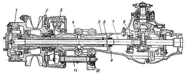
Rice. 71. Rear axle MAZ:
1 - gear; 2 - rear wheel hub; 3 - rear wheel brakes; 4 - locking pin of the axle housing; 5 — a ring of a directing axis; 6 - axle housing; 7 - axle shaft; 8 - central gearbox; 9 — coupled epiploon of a semiaxis; 10 - adjustment lever; 11 - unclamp the brake fist
The adopted structural and kinematic schemes for transmitting torque make it possible to divide it into a central gearbox, directing it to the wheel gears, and thus unloading the differential and axle shafts from the increased torque, which is transmitted in a two-stage scheme from the main gear of the rear axle (as, for example, by car MAZ-200). The use of sprockets also allows, by changing only the number of teeth of the sprocket cylindrical gears and maintaining the center distance of the sprockets, to obtain different gear ratios, which makes the rear axle suitable for use on various vehicle modifications.
The central gearbox (Fig. 72) is single-stage, consists of a pair of bevel gears with spiral teeth and an interwheel differential. The parts of the gearbox are mounted in the crankcase 21 made of ductile iron. The position of the crankcase relative to the beam is determined by a centering shoulder on the flange of the gearbox housing and additionally by pins.
The drive bevel gear 20, made in one piece with the shaft, is not cantilevered, but has, in addition to two front tapered roller bearings 8, an additional rear support, which is a cylindrical roller bearing 7. The three-bear design is more compact, while the maximum radial load on the bearings is significantly reduced Compared with the cantilever installation, the bearing capacity and the stability of the bevel gear meshing installation are increased, which greatly increases its durability. At the same time, the possibility of approaching tapered roller bearings to the crown of the drive bevel gear reduces the length of its shaft and, therefore, allows you to increase the distance between the gearbox flange and the gearbox flange, which is very important with a small carriage base for a better location of the cardan shaft. The outer races of the tapered roller bearings are located in the crankcase 9 and are pressed against the stop into the shoulder made in the crankcase. The flange of the bearing housing is bolted to the rear axle gearbox. These bearings take up the radial and axial loads generated by the meshing of a pair of bevel gears in the transmission of torque.
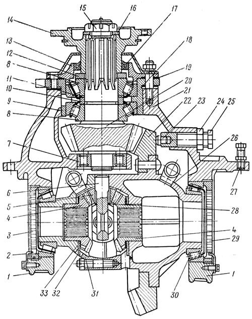
Rice. 72. Central gearbox MAZ:
1 - bearing cover; 2 - bearing nut cover; 3 — a nut of the left bearing; 4 - shaft gear; 5 - differential satellite; 6 - differential cross; 7 - cylindrical bearing of the drive gear; 8 - conical bearing drive gear; 9 - bearing housing of the drive gear; 10 - spacer ring; 11 - adjusting washer; 12 - oil deflector; 13 - stuffing box cover; 14 - flange; 15 - flange nut; 16 - washer; 17 - stuffing box; 18 - wedges; 19 - gasket; 20 - drive gear; 21 - gearbox; 22 - driven gear; 23 - cookies; 24 - locknut; 25 - driven gear limiter; 26 - right differential cup; 27 — a bolt of removal of a transmission; 28 - thrust ring bushing; 29 — nut of the right bearing; 30 - tapered bearing; 31 — a cup of the left differential; 32 - steel washer; 33 - bronze washer
The inner bearing has a tight fit on the shaft and the outer bearing has a slip fit to allow adjustment of the preload on these bearings. Between the inner rings of tapered roller bearings, a spacer ring 10 and an adjusting washer 11 are installed. The required preload of tapered roller bearings is determined by selecting the thickness of the adjusting washer. Cylindrical roller bearing 7 of the transmission bevel gear is installed in the tidal hole of the rear axle gearbox housing along a movable fit and is fixed by an axial displacement with a retaining ring that enters the slot in the bushing at the end of the drive gear.
In the front part of the bevel gear shaft of the transmission, a surface thread of a smaller diameter and a large diameter surface splines are cut, on which an oil deflector 12 and a propeller shaft flange 14 are installed. All parts located on the pinion shaft are tightened with castle nut 15.
To facilitate removal of the bearing housing, its flange has two threaded holes into which tie bolts can be screwed; when screwed in, the bolts rest against the gearbox housing, due to which the bearing housing comes out of the gearbox. Bolts of the same purpose, screwed into the flange of the gearbox housing, can be used as dismantling bolts.
Driven bevel gear 22 is riveted to the right differential cup. Due to the limited clearance between the pinion and the boss in the gearbox housing for additional support of the rear axle drive gear, the rivets connecting the driven gear to the differential cup from the inside have a flat head.
The driven gear is centered on the outer surface of the differential cup flange. During operation, the driven gear may be pressed away from the drive gear as a result of deformation, as a result of which the gear engagement will be broken. To limit this deformation and ensure proper contact in the meshing of the bevel gears, the reducer is equipped with a driven gear limiter 25, made in the form of a bolt, at the end of which a brass cracker is inserted. The limiter is screwed into the gearbox housing until its stop touches the end face of the driven bevel gear, after which the limiter is unscrewed to create the necessary clearance and the nuts are locked.
The engagement of the main gear bevel gears can be adjusted by changing a set of shims 18 of various thicknesses made of mild steel and installed between the bearing housing and the rear axle gearbox housing. A pair of bevel gears at the factory is pre-selected (selected) for contact and noise. Therefore, when replacing one gear, the other gear must also be replaced.
The rear axle differential is tapered, has four satellites 5 and two side gears 4. The satellites are mounted on high-strength steel cross pins and heat-treated to high hardness. The accuracy of the manufacture of the cross 6 ensures the correct relative position of the satellites on it and its proper engagement with the side gears. The satellites are supported on the necks of the transom through bushings made of multi-layered bronze tape. Between the satellites and the bases of the crossheads, 28 steel thrust rings are installed, which securely fix the bushings of the satellites.
The outer end of the satellites adjacent to the differential cup is lapped onto a spherical surface. The support of the satellites in the cup is a stamped bronze washer, also spherical. The satellites are spur bevel gears made of high-strength carburized alloy steel.
The crossbar with four points enters the cylindrical holes formed in the plane of the cups parting during their joint processing. Joint processing of the cups ensures the exact location of the cross on them. The centering of the cups is achieved by the presence of a shoulder in one of them, and the corresponding slots and pins in the other. A set of cups is marked with the same numbers, which must match during assembly to maintain the accuracy of the location of the holes and surfaces obtained during joint processing. If it is necessary to replace one differential cup, the second, i.e. complete, cup must also be replaced.
Differential cups are made of ductile iron. In the cylindrical holes of the hubs of the differential cups, straight-bevel semi-axial gears are installed.
The inner surfaces of the hubs of the semi-axial gears are made in the form of holes with involute splines for connection with the semi-axes. Between the side gear and the cup there is a space corresponding to the wide stroke adjustment, which is necessary to keep the oil film on their surfaces and prevent wear of these surfaces. In addition, two washers are installed between the bearing surfaces of the ends of the semiaxes and the cups: steel 32, fixed turning, and bronze 33, floating type. The latter is located between the steel washer and the side gear. The paddles are welded to the differential cups, providing an abundant supply of lubricant to the differential parts.
The covers for their correct position relative to the gearbox housing are centered on it with the help of bushings and fixed to it with studs. The crankcase holes and differential bearing caps are machined together.
The preload of the tapered roller bearings of the differential is adjusted by nuts 3 and 29. Adjusting nuts made of high-strength cast iron have wrench protrusions on the inner cylindrical surface, with which the nuts are wrapped and fixed in the desired position with locking whiskers. 2, which is attached to the machined front surface of the bearing cap.
Gearbox parts are lubricated with oil sprayed by the ring gear of the driven bevel gear. An oil bag is poured into the gearbox housing, into which the oil sprayed by the driven bevel gear is ejected, and the oil flowing down from the walls of the gearbox housing settles.
From the oil bag, oil is fed through the channel to the pinion bearing housing. The shoulder of this housing separating the bearings has a hole through which oil flows to both tapered roller bearings. The bearings, mounted with cones towards each other, are lubricated with incoming oil and, due to the pumping action of the conical rollers, pump it in different directions: the rear bearing returns the oil to the crankcase, and the front one returns it to the cardan shaft flange.
There is a hardened mild steel baffle between the flange and the bearing. On the outer surface, the washer has a left-hand thread with a large pitch, that is, the direction of the thread is opposite to the direction of rotation of the gear; in addition, the washer is installed with a slight gap in the opening of the stuffing box. All this prevents the lubricant from flowing from the bearing into the stuffing box due to the sealing of the outer surface of the flange.
On the flange side, the bearing housing is closed with a cast-iron cover, into which a reinforced self-supporting rubber gasket with two working edges flush with the outer end is pressed. A slot is made in the mounting shoulder of the cover, coinciding with an inclined hole in the bearing housing. The gasket between the cover and the bearing housing and the wedges 18 are installed in such a way that the cutouts in them coincide with the groove in the cover and the hole in the bearing housing, respectively.
Excess oil that has penetrated into the cavity of the cover is returned to the gearbox through a slot in the cover and an inclined valve in the bearing housing. The reinforced rubber seal is pressed with its working edges against the polished and hardened to high hardness surface of the flange 14, made of carbon steel.
The secondary gear cylindrical roller bearing is splash lubricated only. The tapered roller bearings in the differential cups are lubricated in the same way.
The presence of wheel gears, although it reduced the load on the parts of the differential, but led to an increase in the relative speeds of rotation of the gears when turning or sliding the car. Therefore, in addition to the measures taken to protect friction surfaces (the introduction of support washers and bushings), it is also planned to improve the lubrication system for differential parts. Blades welded to the differential cup take lubricant from the gearbox housing and direct it to the parts located in the differential cups. The abundance of incoming lubricant contributes to the cooling of rubbing parts, their penetration into the gaps, which reduces the possibility of seizing and wear of parts.
Read also Maintenance of KAMAZ electrical equipment
The fully assembled central gearbox is installed in the large hole in the rear axle housing and bolted to its vertical plane with studs and nuts. The mating flanges of the central part of the rear axle housing and gearbox are sealed with a gasket. In the rear axle crankcase, the threaded holes for the crankcase mounting studs are blind, which improves the tightness of this connection.
The rear axle housing is made of cast steel. The presence of holes in the vertical plane practically does not affect the rigidity of the rear axle housing. Its connection with the gearbox is rigid and does not change during the operation of the car. Such fastening in the vertical plane has a great advantage in comparison with the connection of the gearbox with the rear axle housing in the horizontal plane, for example, on the MAZ-200 car, where significant deformations of the open crankcase from above violated its connection with the rear axle housing.
The rear axle housing ends at both ends with flanges to which the brake calipers of the rear wheels are riveted. From the upper side, the spring platforms merge with it into a single whole, and tides are made to these platforms from below, which are guides for the rear spring ladders and support for the nuts of these ladders.
Next to the spring pads are small rubber retaining pads. Inside the crankcase, two partitions are made on each side; in the holes of these partitions of the cylindrical ends of the crankcase, they are pressed by a casing 6 (see Fig. 71) of the axle shafts 7.
Semi-axle boxes due to the presence of wheel gears, in addition to the bending moment from the forces of the weight of the load and the own weight of the car, are also loaded with a reactive moment felt by the gear cups of the wheels, which is firmly attached to the corrugated end of the casing. In this regard, higher requirements are imposed on the strength of the frame. The body is made of thick-walled alloy steel tubing that has been heat-treated for increased strength. The pressing force of the housing to the rear axle housing is not enough to prevent its rotation, therefore the housing is additionally locked on the rear axle housing.
In the crankcase partitions located near the spring platforms, after pressing the body, two holes are drilled, simultaneously passing through the rear axle housing and the axle shaft housing. Inserted into these holes are 4 hardened steel locking pins welded to the rear axle housing. The locking pins prevent the body from rotating in the rear axle housing.
In order not to weaken the crankcase and housing under the action of vertical bending loads, the locking pins are installed in a horizontal plane.
At the outer ends of the axle housings, random splines are cut into which the cup of the wheel gear is placed. On the same side of the body, a thread is cut for fastening the nuts of the wheel hub bearings. Holes for shaft seals 9 7 and guide centering rings 5 are made from the inner ends of the housings. Centering rings guide the shaft during installation, protecting the shaft seals from damage. The shaft seals are two separate self-locking reinforced rubber seals mounted in a stamped steel cage with the sealing lips facing each other.
To eliminate the possibility of increasing pressure in the cavities of the crankcases of the central wheel reduction gears when the oil is heated, three ventilation valves are installed in the upper part of the rear axle housing, one on the left side of the upper part of the rear axle, the semi-axle housing of medium expansion and two near the spring areas. When the pressure in the crankcase cavities increases, the ventilation valves open and communicate these cavities with the atmosphere.
The wheel drive (Fig. 73) is the second stage of the rear axle gearbox.
From the driving bevel gear of the central gearbox, through the driven bevel gear and the differential, the torque is transmitted to the axle shaft 1 (Fig. 74), which supplies the moment to the central gear, called the satellite 2 of the wheel thrust. From the sun gear, rotation is transmitted to three satellites 3, evenly spaced around the circumference around the sun gear.
Satellites rotate on axes 4, fixed in the holes of a fixed support, consisting of external 5 and internal 10 cups, in the direction opposite to the direction of rotation of the sun gear. From the satellites, the rotation is transmitted to the ring gear 6 of the internal gearing, mounted on the rear wheel hub. The ring gear 6 rotates in the same direction as the satellites.
The gear ratio of the wheel drive kinematics scheme is determined by the ratio of the number of teeth on the ring gear to the number of teeth on the sun gear. The satellites, freely rotating on their axles, do not affect the gear ratio, therefore, by changing the number of teeth of the wheel gears while maintaining their distance between the axles, you can get a number of gear ratios, which, even with the same bevel gears in the central gearbox, can provide greater gear ratio selectivity rear bridge.
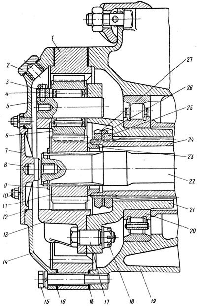
Rice. 73. Wheel drive:
1 - ring gear (driven); 2 - filler plug; 3 - retainer of the axis of the satellite; 4 - the course of the satellite; 5 - axis of the satellite; 5 - satellite; 7 - small cover; 8 - persistent crack of the axle shaft; 9 - retaining ring; 10 - hairpin; 11 - sun gear (leading); 12 - sealing ring; 13 - outer glass; 14 - large cover; 15 — a bolt of a big cover and a ring gear; 16 - gasket; 17 — a cup of a starting bolt; 18 - nut; 19 - wheel hub; 20 - outer bearing of the hub; 21 - driven inner cup; 22 - axle shaft; 23 - drive gear stop; 24 - axle housing; 2S - hub bearing nut; 26 - retaining ring; 27 - wheel bearing locknut
Structurally, the wheel gear is made as follows. All gears are cylindrical, spur. Sun gear 11 (see fig. 73) and satellites 6 - external gear, crown - internal gear.
The sun gear has a hole with involute splines that mate with the splines on the corresponding end of the axle shaft. The opposite inner end of the axle shaft also has twisted splines that mate with the splines in the hub bore of the differential shafts. The axial movement of the central shaft on the axle shaft is limited by the spring retaining ring 9. The axial movement of the axle shaft 22 towards the central gearbox is limited by the central planet fixed on it. In the opposite direction, the movement of the axle shaft is prevented by a persistent crack 8 pressed into the bushing of the small cover 7 of the wheel gear. The satellites are mounted on shafts fixed on a removable bracket consisting of two cups. The inner bowl 21 is forged from carbon steel, has a hub that is cylindrical on the outside and a slotted hole on the inside. The outer cup 13 has a more complex configuration and is made of cast steel. The bearing cups are interconnected by three bolts.
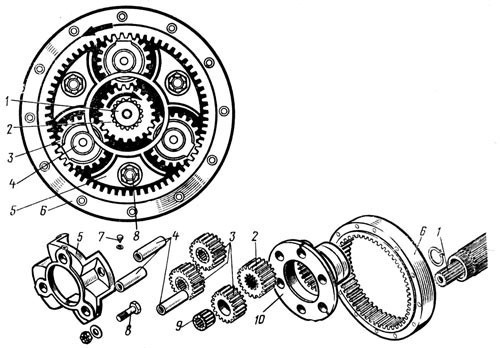
Rice. 74. Wheel drive scheme and its details:
1 - axle shaft; 2 - sun gear; 3 - satellite; 4 - axis of the satellite; 5 - outer cup; 6 - ring gear; 7 - retainer axis of the satellite; 8 - coupling bolt of the carrier cup; 9 - the course of the satellite; 10 - inner cup holder
In the assembled cups of the carrier, three holes are simultaneously processed (drilled) for the axis of the satellites, since the accuracy of the relative position of the satellites in relation to the sun and crown gears determines the correct transmission clutch, gears, and also the durability of the gears. Co-machined wheel hubs are not interchangeable with other hubs and are therefore marked with a serial number. The lugs of the outer cups for the satellite axle holes have threaded holes for the locking bolts of the three satellite axles.
Assembled glasses (wheel holders) are installed on the outer splined part of the axle housing. Before planting the carrier, the inner wheel hub 19 is installed in the crankcase of the axle shaft on two bearings. The double tapered roller bearing of the inner hub is mounted directly on the axle housing, while the outer cylindrical roller bearing is mounted on the wheel carrier. A cast spacer is installed between the double tapered roller bearing and the wheel carrier. Then the assembled bracket is fixed on the axle shaft housing using nut 25 and lock nut 27. A retaining ring 26 is installed between the nut and lock nut, which should enter the groove of the axle housing with an internal protrusion.
The assembled cups of the wheel gears form three holes into which satellites are freely inserted. The satellites have carefully machined cylindrical holes for the installation of 4 cylindrical roller bearings that do not have either outer or inner rings. Therefore, the inner cylindrical hole of the satellite is a knurling belt for support rollers. Similarly, the surface of the satellite shaft plays the role of the inner ring of the bearing. Since bearing life is directly related to the hardness of the raceways, satellite shafts are made of alloy steel and heat treated to obtain a high hardness of the surface layer (HRC 60-64.
When assembling the wheel drive, first, bearings are installed in the hole of the satellite, and then, lowering the gear into the hole formed by the cups, the satellite shaft is inserted into the bearing. The satellite shaft is installed in the cups along the course of adjustment and is fixed in them by rotation and axial displacement with the help of a locking bolt 3, the conical rod of which enters the conical hole at the end of the satellite shaft. To facilitate disassembly of this shaft, there is a threaded hole on its front surface. By inserting a bolt into this hole through the sleeve, leaning on the outer cup of the carrier, you can easily remove the shaft from the satellite.
The gears mesh with both the sun gear and the ring gear.
Torque is transmitted to the main gear through three gears meshed with it, so the teeth of the ring gear are less loaded compared to the teeth of the wheel gear. Operating experience also shows that a gear coupling with an internal gear rim is the most durable. The ring gear is installed and centered with a shoulder in the groove of the rear wheel hub. A gasket is installed between the gear and the hub.
On the outer side, in the center of the collar of the ring gear, there is a large cover 14 that covers the gear. A sealing gasket is also installed between the cover and the gear. The cover and the ring gear are screwed with common bolts by 15 to the rear wheel hub, which is mounted on a bearing mounted on the wheel frame, providing the necessary mutual accuracy of the location of the satellites with support on the axle, precision holes of the same carrier placed during machining and the correct engagement of the satellites with the clockwork head. On the other hand, the sun gear does not have a special support, i.e. it "floats" and is centered on the planetary gear teeth, so the load on the planetary gears is balanced, since they are evenly spaced around the circumference with sufficient accuracy.
The sun gear of the wheel drive and satellites are made of high quality alloy steel 20ХНЗА with heat treatment. The surface hardness of the gear teeth reaches HRC 58-62, and the core of the teeth remains ductile with a hardness of HRC 28-40. The less loaded ring gear is made of 18KhGT steel.
The gears and bearings of the wheel reduction gears are lubricated with spray oil poured into the cavity of the wheel reduction gear. Because the gear chamber consists of a large cover and a rear wheel hub that rotates on tapered bearings, the oil in the gear chamber is constantly agitated to provide lubrication to all gears and gear wheel bearings. Oil is poured through a small cap 7, attached to the large wheel drive cap with three pins and sealed along the centering collar with a rubber sealing ring 12.
With the small cover removed, the lower edge of the hole in the large cover determines the required oil level in the wheel train. The large oil drain plug has a hole closed with a barrel plug. To prevent oil from flowing from the cavity of the wheel gear into the central gearbox, as noted above, a double oil seal is installed on the axle shaft.
Oil from the wheel drive cavity also enters the rear wheel hub cavity to lubricate the double tapered and cylindrical roller bearings of the wheels.
From the inner side of the hub to its end face, through a rubber gasket, the stuffing box cover is screwed, in which a rubber-metal self-locking stuffing box is placed. The working edge of the stuffing box seals the cavity of the hub along a removable ring pressed into the axle housing. The surface of the ring is ground to a high degree of purity, hardened to high hardness and polished. The stuffing box cover on the wheel hub is centered on the shoulder, which at the same time abuts against the outer ring of the double tapered bearing, limiting its axial movement.
In the gland cover, the flange, which is of considerable size, serves as an oil deflector, since there is a small gap between it and the removable gland ring. Also, on the cylindrical surface of the flange, oil-flushing grooves are cut, having an inclination in the direction opposite to the direction of rotation of the hub. To prevent grease from getting on the brake drums, the oil seal is closed with an oil deflector.