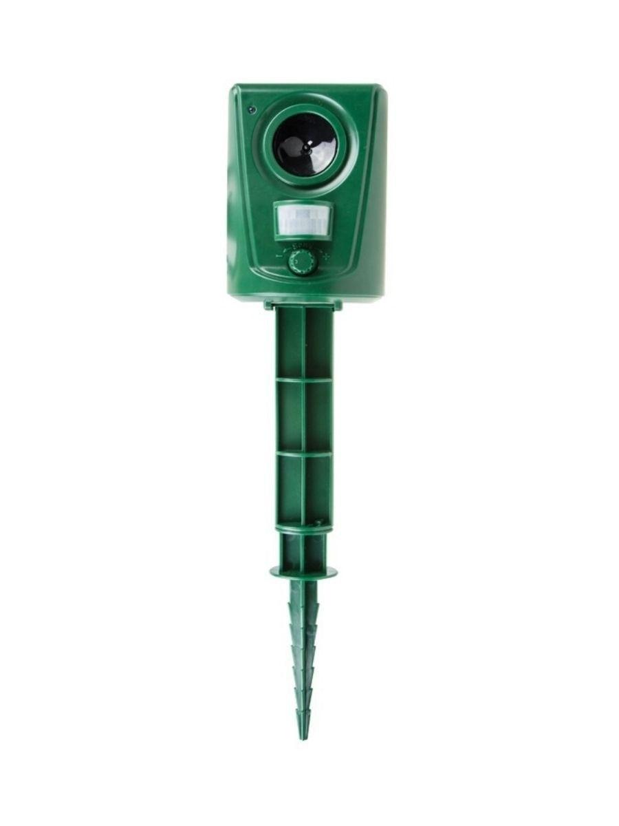
AVT2722 - universal ultrasonic repeller
This time we are presenting a very simple device with which we can get rid of the unwanted company of insects or small animals in various natural conditions…
Compared to similar commercially available systems, this kit is characterized by: the ability to smoothly change the operating frequency and intermittent operation (break / operation time can be adjusted). As a result, the system is much more efficient than similar solutions. The adopted mode of operation leads to the fact that it consumes a small amount of electricity. This means longer operating times without the need to replace the power source (battery). Thanks to a small number of elements and simple assembly, anyone can assemble the putty in just a few minutes.
Electronics is like a mosquito whip!!!
Description of the layout
The main elements of the system are three popular CMOS integrated circuits and a piezo transducer as an electro-acoustic transducer.
The repeller diagram shows fig. 1. Diode D1 serves as protection against the negative effects of a temporary (ie, erroneous) connection of the supply voltage to integrated circuits. The system can be powered by a 9 V battery or higher, up to and including 15 V. This allows you to connect the repeller, for example, to a car (and attach it to the battery), thereby protecting the car, for example, from martens. These small predators love to chew seals and cables in the car. Such surprises are very likely, especially in villages and isolated places.
The system that regulates the duration and breaks of the scare signal is a simple generator built on one of the six Schmitt inverters of the U1 cube. Potentiometer P1 sets the total time - the duration of the "work + break" cycle, and P2 sets its proportions. With the given values of the elements, the maximum duration of a break or work is 36 s, and the minimum is 0,5 s.
Four series inverters U1 were connected in parallel with each other, and their inputs were directly connected to the output of the inverter-generator U1A. Parallel connection of inverters is allowed if they are located on the same chip. The inverters increase the current output of U1A. U1F controls LED D4. The integrated circuit U1 cycles the power on and off for the rest of the cubes U2 and U3. U2A and U2B - generator of high-frequency acoustic signals. Adjustment is made by potentiometer P3. U2C acts as a buffer and U2D reverses the phase of the signal appearing at the output of U2C. This phase reversal is necessary because U3 acts as a bridge amplifier for the signal generated by U2. Such an amplifier slightly increases the efficiency (range) and is needed especially at a lower supply voltage.
Installation and adjustment
Installing a repeller is not difficult for anyone - the location of the elements is shown in fig. 2.
Solder the resistors first. Then - capacitors, semiconductors and potentiometers, and only at the end - power cables and a piezoelectric transducer. Solder capacitor C3 horizontally. The system does not have an on/off switch due to easy battery disconnection and minimal power consumption. The power source can also be an external power supply (filtered and rectified voltage, not necessarily stabilized) or a battery.
After soldering all the elements, connect the power supply and adjust the required operating time, pauses and the frequency of the generated sound with the potentiometers. We determine the timing and frequency experimentally, from time to time observing the effectiveness of intimidation. While for spring-summer and autumn sucking-biting insects (for example, mosquitoes, flies) these frequencies should be in the range of 18-50 kHz, in the case of martens, for example, about 10-20 kHz.
Of course, the efficiency of the described device cannot be guaranteed by XNUMX%, but the possibility of smooth adjustment, of course, allows you to radically increase it. However, this requires experimentation on the part of the user, i.e. monitoring system effects.
When generating a sound with a frequency of several kHz, the system consumed a negligible amount of current - less than 0,5 mA (measured without an LED - with it, depending on the value of the series resistor R6).
