Renault scenic 2 fuse boxes and relay
Content
Renault Scenic 2 generation was produced in 2003, 2004, 2005, 2006, 2007, 2008, 2009 and 2010. The 7-seat version is also known as the Grand Scenic. During this period, the car was updated once, but only slightly. We will show where the relay and fuse boxes are located on the second generation Renault Scenic. We will provide photographs of blocks, diagrams, describe the purpose of their elements.
Fuses and relays in the passenger compartment
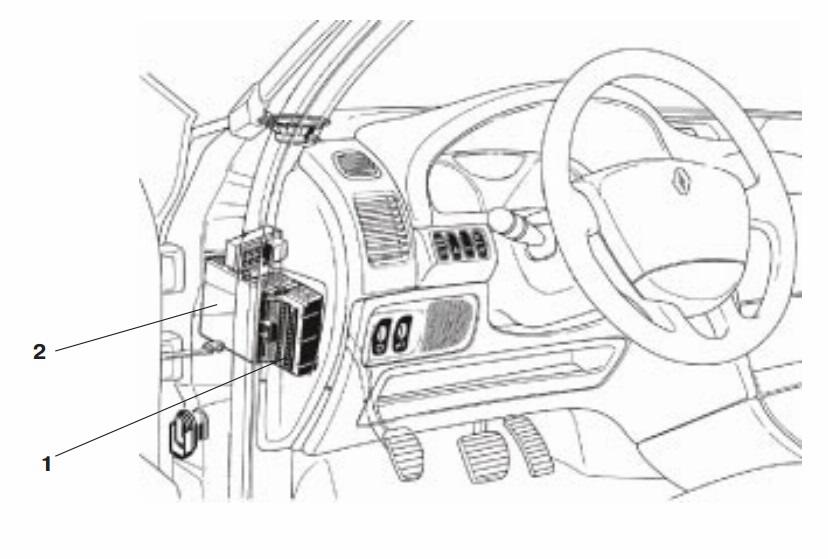
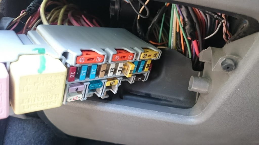
Main unit
It is located on the instrument panel, on the left.
The fuse diagram will be placed on the protective cover.
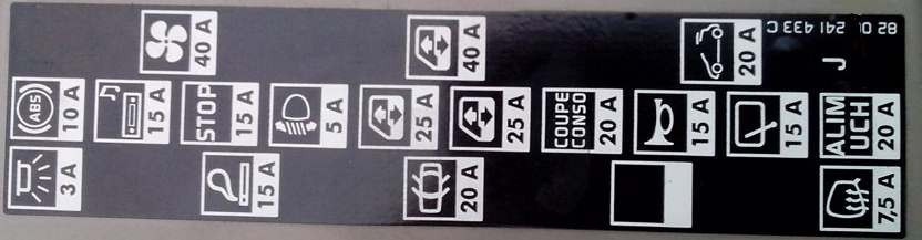
scheme
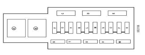
Description
- A - 40A Power Window Relay or Xenon Bulb Relay
- B - 40A Brake light relay
| С | Internal electric fan 40A |
| Д | 40A Pulsar Rear Door Window Regulator or Power Window Relay (Left Hand Drive Vehicles) |
| Me | Electric sunroof 20A |
| Ф | 10A ABS and Trajectory ECU - Angular and Lateral Acceleration Sensor |
| GRAM | 15A Audio system, headlight washer pump relay, front row ignition, seat heaters, windshield washer pump, diesel heating relay, climate control panel, climate control ECU, electrochromic rearview mirror, burglar alarm, central communication unit |
| TIME | 15A brake light |
| К | 5A Xenon ECU Power Relay, Xenon Drive Power Supply, Glove Box Light |
| Л | 25A Power window driver's door |
| METER | 25A Passenger's window regulator, window regulator relay (right-hand drive vehicles) |
| North | 20A Fuse for disconnecting consumers of electricity: audio systems, electric exterior mirrors, burglar alarms, dashboard, center console |
| OR | 15A Horn, diagnostic connector, headlight washer pump relay |
| П | 15A Rear wiper motor |
| Р | 20A UCH, A/C ECU, Stop Lamp Relay (B) |
| Т | Cigarette lighter fuse 15A Renault Scenic 2 |
| Yes | 3A Electric fan and temperature sensor in the cabin, rear-view mirror with electrochromic coating, rain and light sensors |
| You | 20A Central locking or interior door handle locking system |
| В | Not used |
| Tues | 7,5A Mirror Resistors |
The fuse marked with the letter T is responsible for the cigarette lighter, see diagram.
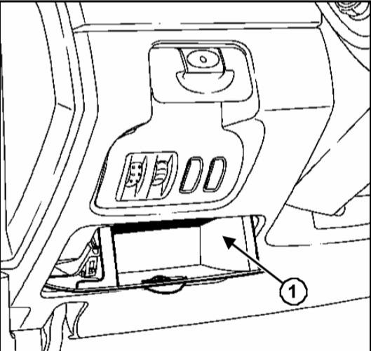
Block under the passenger seat
It is located in the cabin under the left front seat.
Photo
scheme

designation
| а | 25A Automatic parking brake fuse |
| two | 20A Driver and passenger seat heating circuit fuse |
| 3 | 10A Not used |
| 4 | 10 amp fuse for console accessory port, power console latch, and center glove box light |
| 5 | 10A Fuse in accessory socket 2nd row |
| 6 | 10A fuse for accessory socket in the first row of seats |
| К | 50A Power input relay, second power relay for fuses 2, 4, 5 and 6 above |
Individual relays
One pair is located to the right of the UCH (2 auxiliary heater relays) and the relay on the crossmember on the left side of the instrument panel (flow switch in the fuse box)
Blocks under the hood of Renault Scenic 2
You can see the general layout of the blocks and how to access them in this video.
Fuses in the switching unit
block 1
Flowchart 1
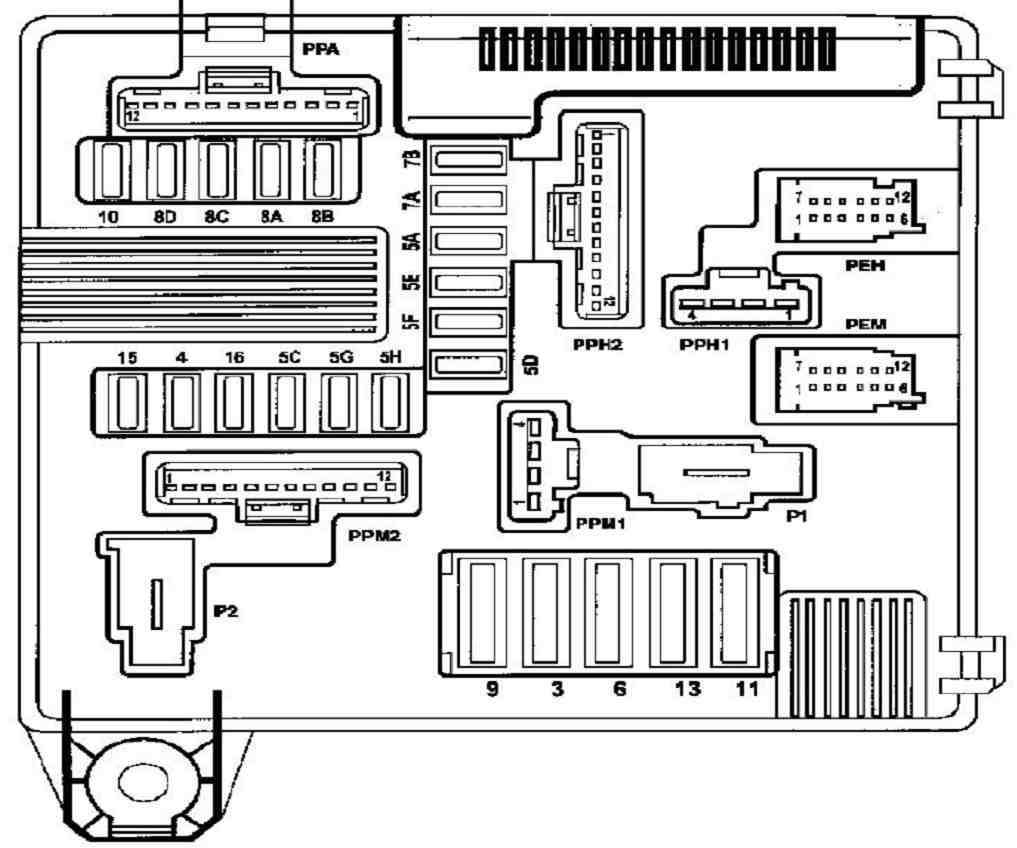
transcribed
| 3 | Starter relay 25A |
| 4 | 10A Clutch for starting the air conditioning compressor |
| 5А | 15A Electric steering column lock |
| 5S | Reversing lights 10A |
| 5 D | 5A ECU of the injection system and electric steering column lock ("+" after the ignition switch) |
| 5Э | 5A airbag and power steering (+after ignition) |
| 5th floor | 7,5A "+" after the ignition switch (in the cab): selector lever position indicator, regulator and speed limiter, fuse and relay box in the cab, auxiliary heater relay, diagnostic connector, rear-view mirror, rain and solar radiation intensity sensor ( depending on modification, computer, audio system |
| 5 hours | 5A automatic transmission |
| 5G | 10A Not used (or "+" after the ignition switch to the liquefied gas supply system, if any) |
| 6 | 30A rear window resistor |
| 7А | 7,5A Right position lights, parking brake system switch, trajectory stabilization system switch, selector lever position indicator, parking brake control knob |
| V7 | 7,5A Left position lights, cigarette lighter, alarm and central locking switches, headlight range control switch, A/C control panel, passenger door power window switch, back door power window switch, navigation ECU, driver and passenger seat heaters |
| 8А | 10A Right headlight (high beam) |
| V8 | 10A Left headlight (high beam) |
| 8S | 10A Low beam (right headlight), headlight range control, right headlight range control actuator, xenon lamp ECU |
| 8D | 10A Left headlight (dipped beam), left headlight corrector drive |
| 9 | Wiper motor 25A |
| 10 | 20A fog lights |
| 11 | 40A Electric fan of the engine cooling system (low speed) |
| thirteen | 25A ABS and trajectory stabilization systems |
| fifteen | 20A + battery for automatic transmission (or LPG system, if available) |
| sixteen | 10A Not used |
block 2
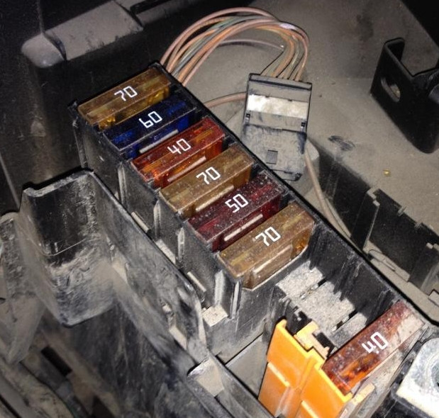
Block diagram 2

Goal
| а | 70A Additional heating relay 2 |
| two | 60A fuse and relay mounting block in cab |
| 3 | 40A Additional heating relay 1 |
| 4 | 70A electric power steering |
| 5 | ABS control unit 50A |
| 6 | 70A Cab Mount Fuses and Relays |
| 7 | 20A Diesel fuel filter heater relay |
| 8 | Preheating control unit 70A |
| 9 | Not used |
Battery fuses
Fusible inserts are located on the positive terminal of the battery.
- 30A - Electronic control unit in the cabin
- 350 A - gasoline vehicle, 400 A - diesel vehicle - engine compartment junction box
- 30A - Engine compartment switch box