Citroen C4 fuse and relay boxes
Content
The first generation Citroen C4 was produced in 2004, 2005, 2006, 2007, 2008, 2009 and 2010 in various modifications: hatchback, picasso, etc. 2017, 2018 and now. We will consider the Citroen C4 fuses with a detailed description of all the blocks and their location.
Depending on the configuration and year of manufacture, several options for the execution of blocks and the placement of the relay are possible.
Fuse blocks under the hood
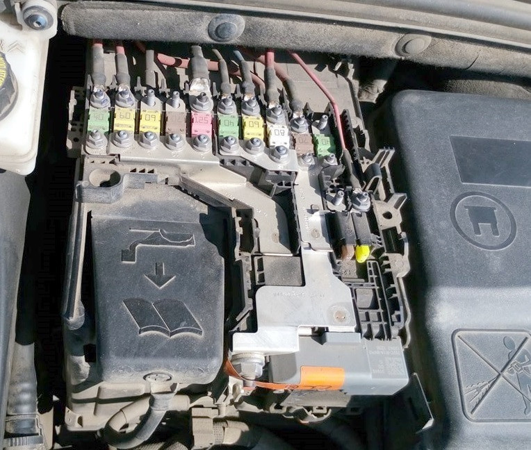
Main unit with fuses
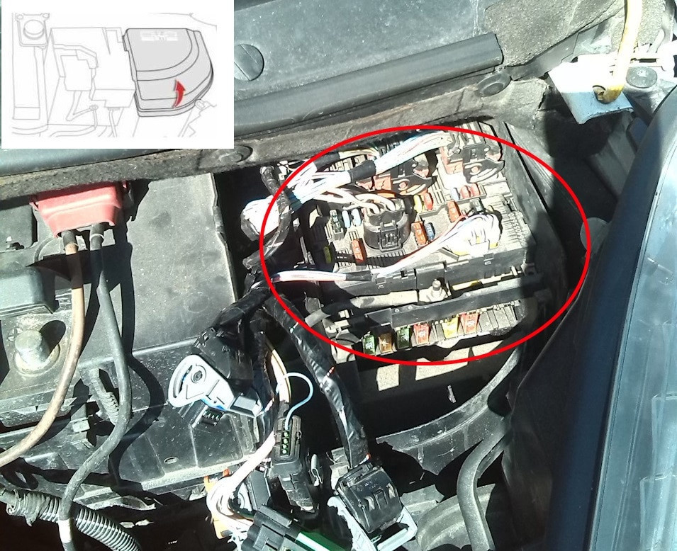
Located next to the battery. To access the fuse box in the engine compartment, disconnect and remove the protective cover.
Option 1
Overall plan
Description
- F1 15A Engine control computer - power distribution and protection unit
- F2 5A Electric fan control unit
- F3 5A Engine control computer
- F5 15A Engine control computer
- F6 20A Engine ECU - fuel pump with fuel level sensor
- F7 10A Engine control computer
- F8 10A Engine control computer
- F10 5A Cruise control safety switch - automatic transmission computer
- F11 15A Left headlight - right headlight - ionizer
- A/C compressor F14 25A
- F15 5A Power steering pump mechanism
- F17 10A Electrochromic interior rearview mirror - driver's door/power window exterior mirror control panel
- F19 30A High/Low Wiper Speed
- Washer pump F20 15A
- F21 20A Headlight washer pump
- F22 15A Horn
- F23 15A Right headlight
- F24 15A Left headlight
- A/C compressor F26 10A
- Starter F29 30А
Separately (at the bottom of the block) are the following fuses:
F10 5A Automatic transmission control group
F11 5A shift lock relay
F12 15A Automatic transmission computer
Option 2
scheme
designation
- 20 A Engine control, engine cooling fan
- Horn 15A
- 10 Windshield and rear window washers
- 20 Headlight washer
- 15A fuel pump
- 10A Automatic transmission, xenon lamps, dimmable headlights, solenoid valve cartridge purge
- 10 A ABS/ESP control unit, power steering
- 25 starting amps
- 10 A Additional heater unit (diesel), coolant level sensor
- 30 A Engine solenoid valve, water-in-fuel sensor, engine ECU, injectors, ignition coil, lambda probe, canister purge solenoid valve (vehicles with 1.4i 16V and 1.6i 16V engines)
- 40 A Fan, air conditioning
- 30A Front wiper
- BSI 40A unit
- Not used
- 10 A Right high beam
- 10 A Left high beam
- 15 A Left low beam
- 15 A Right dipped beam
- 15 Engine computer (vehicles with 1.4i 16V and 1.6i 16V engines)
- Engine solenoid valves 10 A
- 5 A Relay for electric fan of the engine cooling system, variable valve timing systems
Option 3
scheme
transcribed
- (20A) (Engine control module - engine fan group).
- (15A)(Audible signal).
- (10A) (front and rear windshield washers).
- (20A (headlight washer).
- (15A) (fuel pump).
- (10A) (Automatic transmission - Xenon - Adjustable headlights - Canister cleaning solenoid valve (engine 2.0).
- (10A) (ABS/ESP control unit - power steering).
- (20A)(Starter).
- (10A) (Auxiliary Heater Control Module (Diesel) - Water Level Switch).
- (30A) (Engine solenoid valve - water in diesel sensor - engine control unit - injectors - ignition coil - oxygen sensor - canister cleaning solenoid valve (1.4 and 1.6 engines).
- (40A)(Fan - Air conditioning).
- (30A) (Front wiper).
- (40A)(smart switch box).
- (30A) (Air compressor (in 2.0 engine).
Maxi fuses
These fuses are designed as fuses and are located at the bottom of the block.
MF1 30A/50A Engine cooling fan
MF2 ABS/ESP pump power supply 30 A
ABS/ESP calculator MF3 50 A
BSI MF4 80A unit
BSI MF5 80A unit
MF6 10 A Fuse box in passenger compartment
MF7 20 A Diagnostic connector / diesel fuel additive pump
MF8 Not used
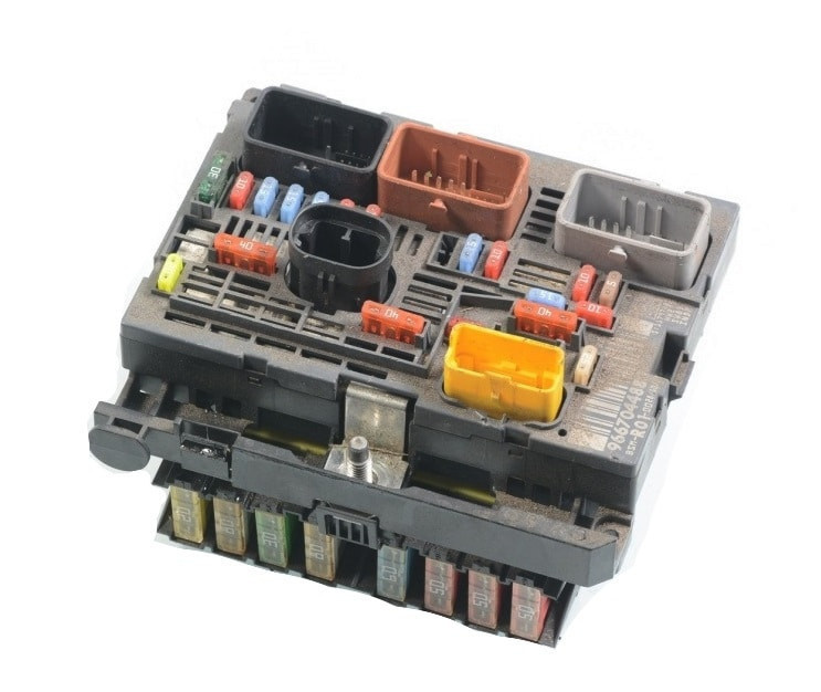
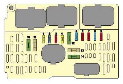
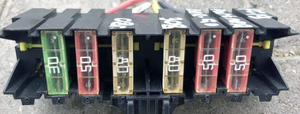
Fuses on the battery
Photo - an example of execution
Option 1
scheme

Description
| а | — |
| two | — |
| 3 | (5A) Battery status sensor |
| 4 | (5A) Transmission control module |
| 5 | (5A/15A) Diagnostic connector (DLC) |
| 6 | (15A) Electronic transmission control unit |
| 7 | (5A) ABS ESP control unit |
| 8 | (20A) Rear socket 12V |
| FL9 | (60A) Fuses at BSI (Intelligent Power Distribution Module) |
| FL10 | (80A) Power steering |
| FL11 | (30A) Electronic transmission control unit |
| FL12 | (60A) Cooling fan motor |
| FL13 | (60A) Fuses at BSI (Intelligent Power Distribution Module) |
| FL14 | (70A) Glow plugs |
| FL15 | (100A) Protection relay box Relay 3 |
| FL16 | — |
Option 2
Block diagram
Goal
- F1 Not used
- F2 30 A Transmission (mechanical with electronic control or automatic transmission)
- F3 Not used
- F4 Not used
- F5 80 A Electric power steering pump
- F6 70 A Heater unit (diesel engine)
- F7 100 A Protection and switching unit
- F8 Not used
- F9 30 A Electric pump assembly with electronically controlled manual transmission
- Engine F10 30A Valvetronic
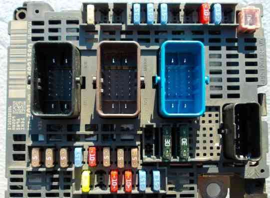
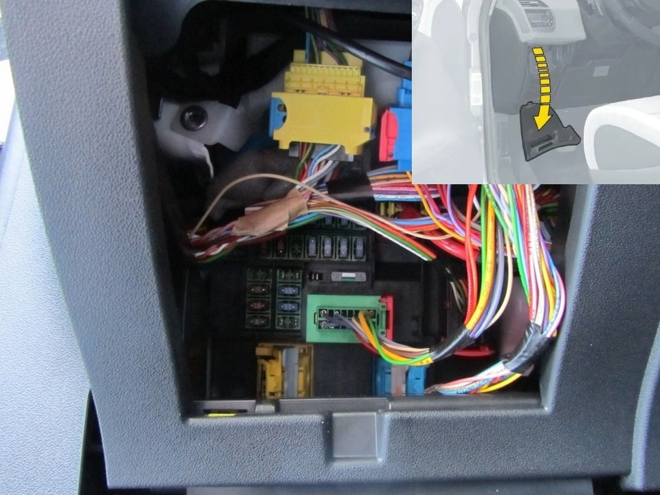
Fuses in the cabin of the Citroen c4
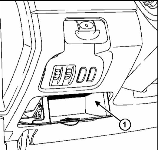
They are located to the left of the driver under the dashboard. Access to them is closed by a decorative cover. To open this cover, you must: release the latches, to do this, pull it from above, then remove the cover, unscrewing the 2 bolts by 1/4 turn, tilt the unit. On the reverse side of the frame, special tweezers are fixed, with which you can easily disassemble any fuse.
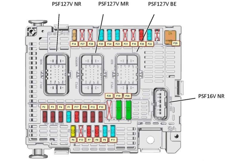
Option 1
Block diagram
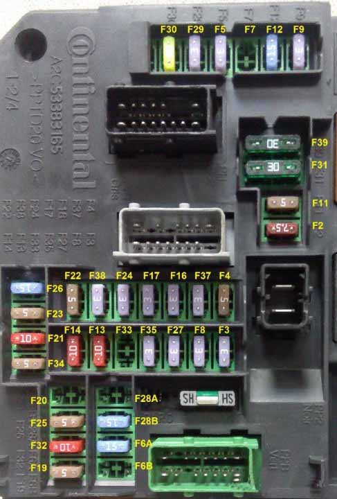
Fuse designation
Diagnostic connector F2 7,5A.
F3 3A Anti-theft device or START/STOP.
F4 5A Remote key reader.
F5 3A Remote control with key.
F6A-F6B 15A Touch screen, audio and navigation system, CD player, USB and auxiliary sockets.
F7 15A Hands free start assist electronics.
F8 3A Burglar Siren, Burglar Alarm Processor.
F9 3A Steering wheel switch box.
F11 5A Stability control ECU, general alarm unit, electronic key scanner.
F12 15A Dual brake pedal contactor .
F13 10A Front cigarette lighter.
F14 10A Rear cigarette lighter.
F16 3A Individual lighting, glove compartment lighting.
F17 3A Parasol lighting, individual lighting.
F19 5A Instrument panel.
F20 5A Electronically controlled manual transmission selector.
F21 10A Car radio and air conditioning.
F22 5A Displays, parking sensors.
F23 5A Fuse box in the engine compartment.
F24 3A Rain and light sensor.
F25 15A Airbag and pyrotechnic pretensioner unit.
F26 15A
F27 3A Dual brake pedal contactor.
F28A-F28B 15A Car radio, car radio (accessory).
F29 3A Turn on the steering column.
F30 20A Rear window wiper.
F31 30A Electric motors for central locking, front and rear external and internal locks.
Rear view camera power supply F32 10A in C4L China. (output 16V NE 13pin), sound amplifier.
F33 3A Driver's seat position memory unit.
F34 5A Power steering relay.
F353A
F37 3A Windshield wiper/rearview mirror control - electrochromic interior rearview mirror
F38 3A Headlight adjustment switch - electrochromic rear view mirror.
F39 30A
Fuses are responsible for the cigarette lighter: 13 and 14.
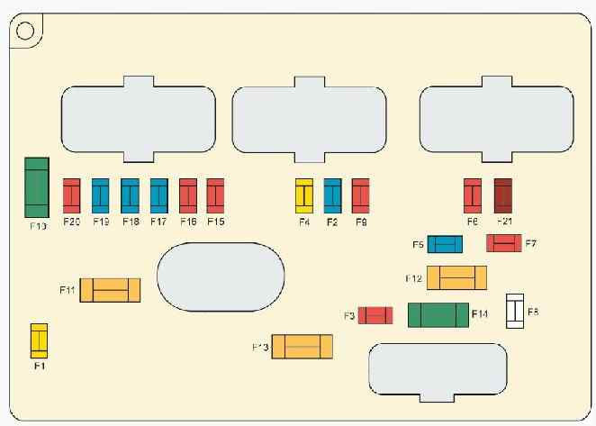
Option 2
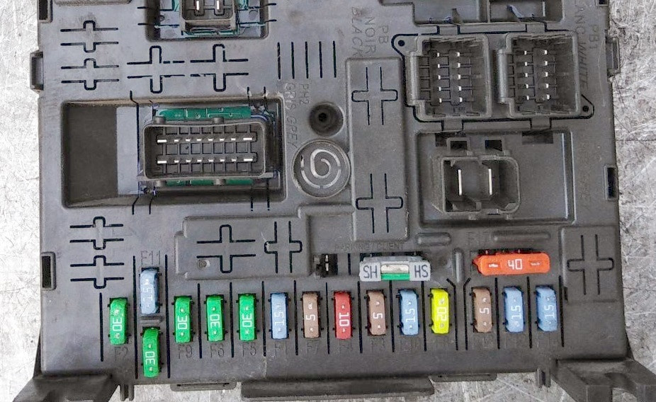
scheme

transcribed
- F1(15A) Rear wiper.
- F2(30A) Central lock - Superlock.
- F3(5A) Airbags and pretensioners.
- F4(10A) Diagnostic connector - Stop light switch - Electrochromic mirror - Dynamic Stability Program (ESP) - Water level sensor - Diesel fuel additives - Clutch pedal speed sensor (ESP, cruise control and speed limiter.
- F5(30A) Front power windows - Power and heated mirrors.
- F6(30A) Rear power windows.
- F7(5A) Interior lighting.
- F8(20A) Car radio - NaviDrive - Steering wheel controls - Screen - Anti-theft alarm - Front 12V socket - Trailer connector - Driving school module.
- F9(30A) Cigarette lighter - 12V rear socket.
- F10(15A) Tire pressure sensors - BVA - STOP contactor.
- F11(15A) Anti-theft steering lock - Diagnostic connector - Diesel particulate filter.
- F12 (15A) Electric seats - Lane crossing warning - Parking sensors.
- F13 (5A) Rain sensor - Light sensor - Electronic manual transmission - Engine control unit.
- F14 (15A) Air conditioning - Dashboard - Tachometer - Airbags and pretensioners - Trailer connector - Bluetooth telephone.
- F15(30A) Central lock - Superlock.
- F16(BYPASS)(—).
- F17(40A) Heated rear window.
- F29(20A) Seat heating.
- F33(4A) Parking assistance system, automatic wipers and lights.
- F36 (20A) High quality amplifier.
- F37 (10A) Air conditioning.
- F38 (30A) Power driver's seat.
- F39 (5A) Filling nozzle.
- F40 (30A) Power passenger seat, panoramic roof.
Fuses number 8 and 9 are responsible for the cigarette lighter.
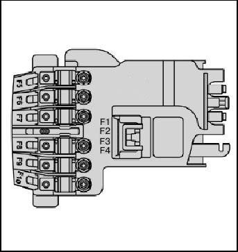
Relay and fuse box - BFH3
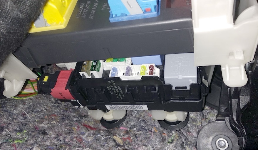
Located just below the main.

Block elements
| F3 | Fuse box 15A in cabin 5 for taxi version |
| F4 | 15A 12V socket for multimedia equipment |
| F5 | Rear window motors 30A |
| F6 | Front window motors 30A |
| F7 | Seat heating 2A |
| F8 | 20A air conditioning fan |
| F9 | Power trunk lid 30A |
| F10 | Left seat belt reel 40A |
| F11 | Trailer Junction Box 5A |
| F12 | 30A power driver's seat and massage device |
| F13 | Right Belt Coil 40A |
| F14 | Replacement Handles 30A - Power Passenger Seat - Seat Massage Devices |
| F15 | 25A sunroof motor |
| F16 | 5A multiplex window/mirror door controller control board |
| F17 | 10A lighting unit and exterior mirror position memory |
| F18 | 25A audio amplifier |
| F19 | not used |
| F20 | 7,5A power trunk lid |
| F21 | 3A hands-free access and start lock |
| F2 | Electrically heated mirrors 7,5A |
| F22 | Socket 20A 230V |
| F23 | not used |
| R1 | 230V plug |
| R2 | 12V socket |
| R3 | not used |
| F1 | Heated rear window 40A |
Separate safety relays can be installed outside of these units, and located next to their protection device (for example, a cooling fan relay, etc.)
Additional Information
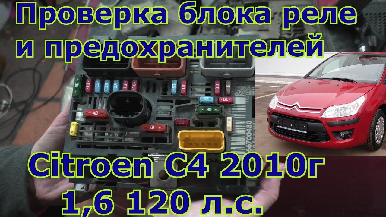
On our channel, we also prepared a video for this publication. Watch and subscribe.
The C4 Picasso and Grand Picasso models have a wider range of equipment and we have prepared a separate article for them here. You can read it if you didn't find the answer to your question.
And if you know how to improve the article, write in the comments.