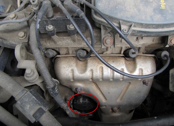
Abs sensor KAMAZ 65115
Content
- Wiring diagram for KAMAZ 5490
- Components of the electrical circuit KAMAZ 5490
- Fuse diagram KAMAZ 5490
- Fuse relay block KAMAZ 5490, 65206 65207
- Relay
- Scheme KAMAZ 5490 Switching unit
- Scheme KAMAZ 5490 Engine control unit
- Electric circuit ABS KAMAZ (mercedes) - Auto parts and auto parts
- Brake ESU Components
- The principle of operation of ABS on KamAZ
- ABS malfunctions on KamAZ
- Prevention of the ABS system
- Advantages of KAMAZ with an installed ABS system
Scheme KAMAZ 5490 Electrical diagrams of electrical equipment. Scheme of electrical equipment KAMAZ 5490 fuse scheme Scheme of electrical equipment KAMAZ 5490 NEO with Mercedes-Benz OM457LA engine. As well as KamAZ-5490 error codes and their decoding.
Wiring diagram for KAMAZ 5490
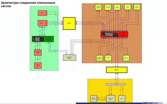
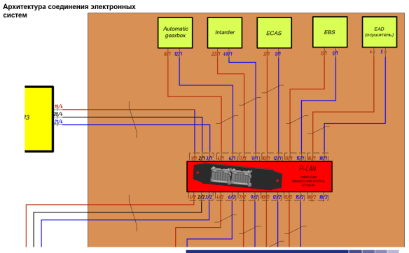
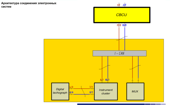
General diagram of electrical systems of electrical equipment KAMAZ 5490.

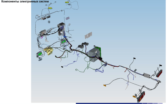
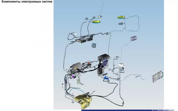
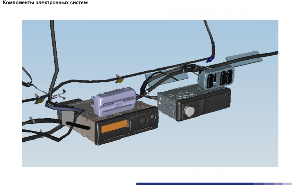
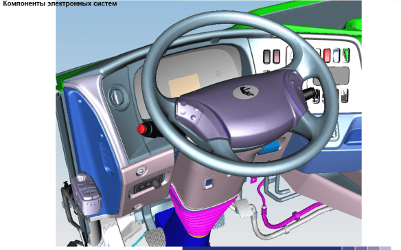
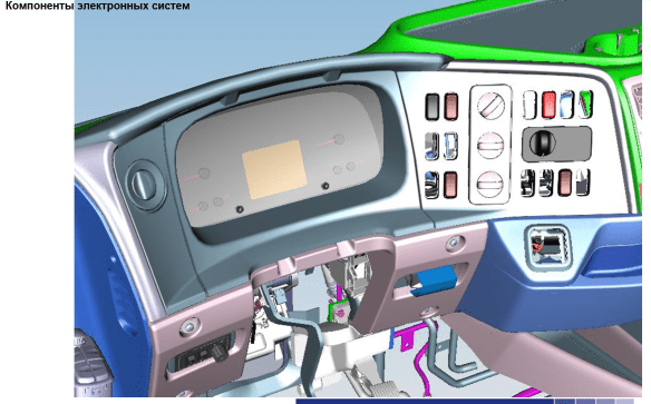
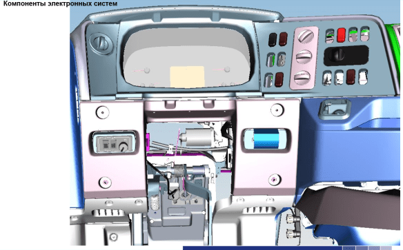
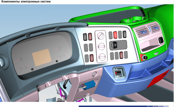
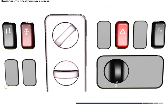
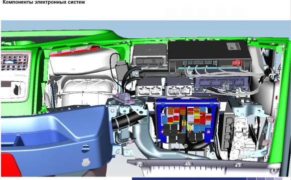
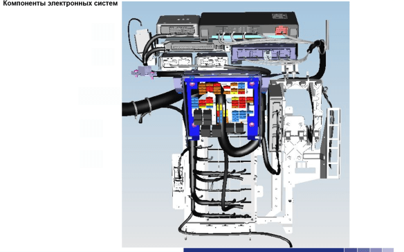
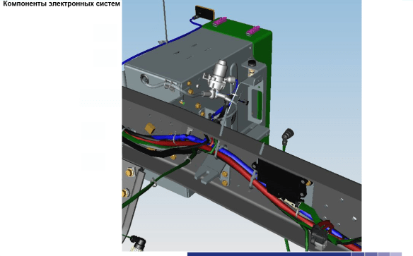
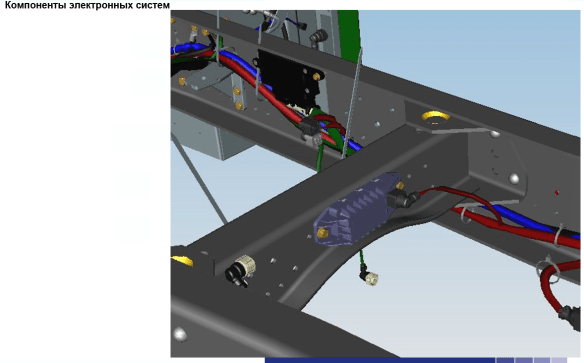
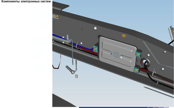
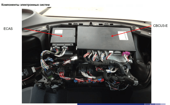
Components of the electrical circuit KAMAZ 5490
Electrical diagram and wiring diagram of KAMAZ 5490:


Fuse diagram KAMAZ 5490
Fuse diagram KAMAZ 5490 NEO and its components:
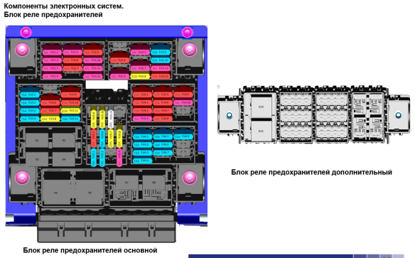
Fuse relay block KAMAZ 5490, 65206 65207 | |||
| designation | Nominal | Consumer | Main Power/Power Switch Status |
| FU1.1 | 5А | EFU control unit | Turn on/turn on |
| FU1.2 | 5А | Air suspension control unit | Turn on/turn on |
| FU1.3 | 5А | Electrical Control Unit (CBCU) | Turn on/turn on |
| FU1.4 | 5А | EBS control unit | Turn on/turn on |
| FU1.5 | 5А | Engine control unit ADM3 | Turn on/turn on |
| FU1.6 | 10А | Neutralization system control unit | Turn on/turn on |
| FU1.7 | 10А | MP2 engine control unit | Turn on/turn on |
| FU1.8 | |||
| FU1.9 | 10А | Retarder control unit | Turn on/turn on |
| FU1.10 | 5А | OBD diagnostic connector | Turn on/turn on |
| FU1.11 | 5А | Tachograph/dashboard | Turn on/turn on |
| FU1.12 | 5А | Connector for special accessories | Turn on/turn on |
| FU2.1 | |||
| FU2.2 | 10А | Driver's side control panel | Turn on/turn on |
| FU2.3 | |||
| FU2.4 | 5А | Generator field winding | Turn on/turn on |
| FU2.5 | 5А | Central locking control unit | Turn on/turn on |
| FU2.6 | |||
| FU2.7 | 5А | Sunroof control drive | Ignition/ACC |
| FU2.8 | A 20 | Air conditioning | Ignition/ACC |
| FU2.9 | 15А | Driver's side control panel | Ignition/ACC |
| FU2.10 | 15А | Passenger door control panel | Ignition/ACC |
| FU2.11 | 5А | Audio system | Ignition/ACC |
| FU2.12 | 10А | Easier | Ignition/ACC |
| FU3.1 | 15А | EBS control unit | On / 0 |
| FU3.2 | 15А | EBS trailer | On / 0 |
| FU3.3 | 15А | Air suspension control unit | On / 0 |
| FU3.4 | 15А | Dehumidifier | On / 0 |
| FU3.5 | |||
| FU3.6 | 10А | Retarder control unit | On / 0 |
| FU3.7 | 10А | Tool combination | On / 0 |
| FU3.8 | A 20 | EFU control unit | On / 0 |
| FU3.9 | 10А | OBD diagnostic connector | On / 0 |
| FU3.10 | 10А | Electric control box | On / 0 |
| FU3.11 | A 20 | Electric control unit CBCU gr.4 | On / 0 |
| FU3.12 | 15А | EBS control unit | On / 0 |
| FU4.1 | A 20 | Electric cabin lift/lower pump | On / 0 |
| FU4.2 | 10А | Inner Light | On / 0 |
| FU4.3 | 10А | Connector for special accessories | On / 0 |
| FU4.4 | 5А | Power supply for keys and sensors | On / 0 |
| FU4.5 | 10А | Audio system | On / 0 |
| FU4.6 | 10А | Glass heating | On / 0 |
| FU4.7 | 10А | headlight hitch | On / 0 |
| FU4.8 | 10А | Plug 24V | On / 0 |
| FU4.9 | 10А | Sound signal | On / 0 |
| FU4.10 | 5А | Remote battery start relay | On / 0 |
| FU4.11 | |||
| FU4.12 | |||
| FU5.1 | 15А | Fuel heating at the fuel inlet | Does not depend / 0 |
| FU5.2 | 15А | Fuel heating in FGOT | Does not depend / 0 |
| FU5.3 | |||
| FU5.4 | 5А | Tachograph | Does not depend / 0 |
| FU5.5 | 10А | Engine control unit ADM3 | Does not depend / 0 |
| FU5.6 | 15А | Neutralization system control unit | Does not depend / 0 |
| FU5.7 | A 20 | Electric control unit CBCU gr.1 | Does not depend / 0 |
| FU5.8 | A 20 | Electric control unit CBCU gr.2 | Does not depend / 0 |
| FU5.9 | A 20 | Electric control unit CBCU gr.5 | Does not depend / 0 |
| FU5.10 | A 20 | Electric control unit CBCU gr.6 | Does not depend / 0 |
| FU5.11 | 25А | PZD | Does not depend / 0 |
| FU5.12 | |||
| FU6.1 | 15А | Electrical control unit MUX4-P | Does not depend / 0 |
| FU6.2 | 15А | Electrical control unit MUX4-P | Does not depend / 0 |
| FU6.3 | 15А | Electrical control unit MUX4-P | Does not depend / 0 |
| FU6.4 | 15А | Electrical control unit MUX4-P | Does not depend / 0 |
| FU6.5 | 15А | Electrical control unit MUX4-P | Does not depend / 0 |
| FU6.6 | 15А | Electrical control unit MUX4-P | Does not depend / 0 |
| FU6.7 | 15А | Heated seat | |
| FU6.8 | |||
| FU6.9 | 15А | Central locking control unit | On / 0 |
Relay | |||
| K1 | Wiper relay | ||
| K2 | Wiper Brake Relay | ||
| K3 | Relay with light latching | ||
| K4 | Horn relay | ||
| K5 | Fuel heater relay | ||
| K6 | Cab tilt lock relay | ||
| K7 | Battery Disconnect Interlock Relay | ||
| K8 | Air conditioner relay |
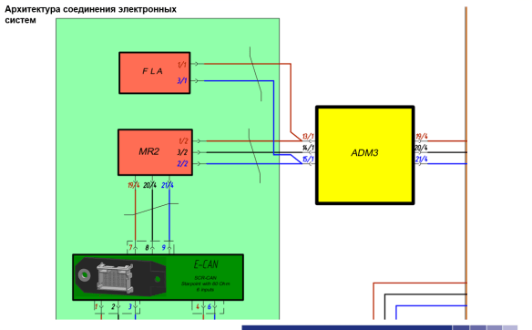
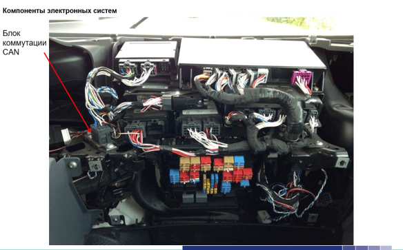
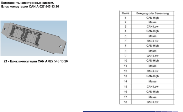
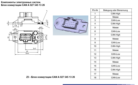
Scheme KAMAZ 5490 Switching unit
CAN A 027 545 13 26 Switching unit and electrical circuit elements of KAMAZ 5490.
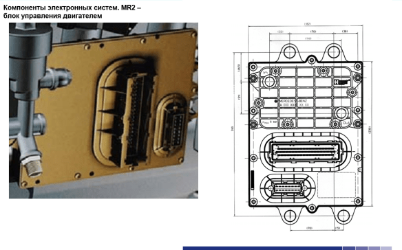
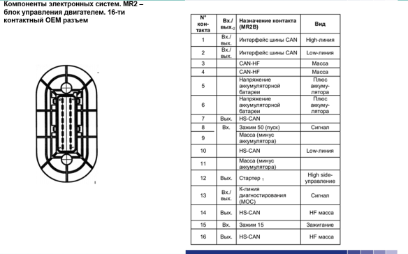
Scheme KAMAZ 5490 Engine control unit
Diagram of the MR2 engine control unit and diagnostic systems.
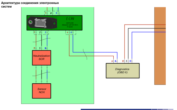
Electric circuit ABS KAMAZ (mercedes) - Auto parts and auto parts
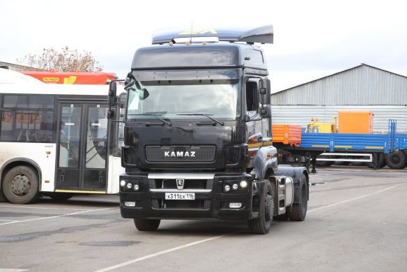
In modern KamAZ vehicles, an anti-lock braking system (ABS) is used. This system helps to reduce accidents when braking. Next, we will talk in more detail about the operation of the system, malfunctions and maintenance to prevent failure of the brake control system. Here you will get answers to all questions. Read more:
- Components of the electronic control system
- The principle of operation of ABS on KamAZ
- ABS Brake Control System Malfunction
- Breakdown prevention and repair tips
- Advantages of a KamAZ truck with an ABS system
Brake ESU Components
The electronic brake control system consists of the following elements:
- Control device
- Brake modulator
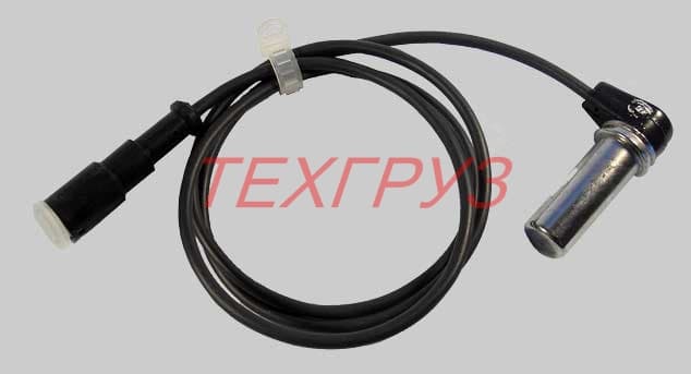
- Wheel rotation sensors
- Channel data line
- Wire harness
The principle of operation of ABS on KamAZ
The electronic control unit constantly receives a signal from the wheel speed sensors. When you press the brake pedal, the control unit receives a signal that the braking process has begun and sends a signal to the modulator via the truck CAN bus to activate the solenoid valves that supply air to the brake pads. Air is supplied to the pads not constantly, but in pulses. As a result of this, the wheels do not "tow", but periodically rotate. If any wheel hits a road surface with different coefficients of friction, the system adjusts the amount of brake pad compression to prevent the vehicle from skidding.
ABS malfunctions on KamAZ
In trucks of this brand, the following malfunctions of the anti-lock braking system occur when the ABS stops working and braking efficiency decreases:
- Wheel speed sensor damage
- Brake Pedal Sensor Malfunction
- Electrical wiring damage
- CAN line faults
- Malfunction of the electronic control unit
- Wheel bearing kit
- Modulator error
Prevention of the ABS system
To prevent failure of the ABS system, it is necessary to periodically diagnose the system. If there is play in the wheels, immediately eliminate it, if necessary, replace the wheel bearings. In case of damage to the wiring, put it in order.
Advantages of KAMAZ with an installed ABS system
Trucks fitted with anti-lock brakes have the following advantages:
- Prevents the truck from skidding when braking
- Reduces stopping distance
- Increases the controllability of KamAZ when braking
Wiring diagram (ECU) of the KAMAZ electronic engine control system with the BOSCH MS6.1 electronic unit. The numbering of the wires in the diagram corresponds to the numbering of the wires in the bundle.
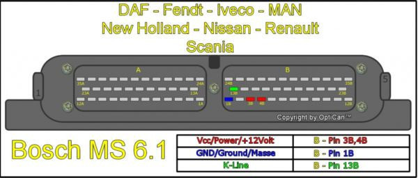
BOSCH MS6.1 ECU connection diagram. KAMAZ
Click on the diagram to enlarge

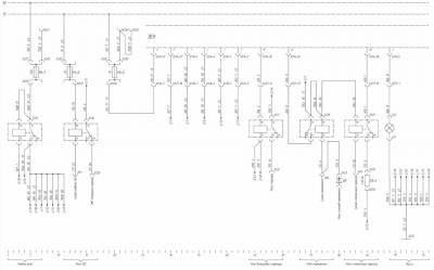
Sheet 1 of the electric circuit of the BOSCH MS6.1 ECU. KAMAZ
Describes air shut-off valve switching, pump connection, charge air temperature and pressure sensor, speed sensor, additional speed sensor, fuel temperature sensor, coolant temperature.
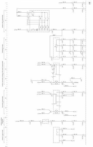
Card 2 of the electrical circuit of the BOSCH MS6.1 ECU. KAMAZ
Described, switching of the main relay, ABS relay, start inhibit relay, brake relay, parking brake relay, ground connection.
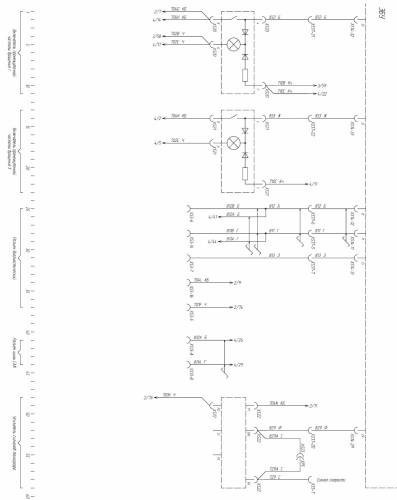
Card 3 of the electrical circuit of the BOSCH MS6.1 ECU. KAMAZ
Described, cruise control switch, accelerator pedal, cruise control/speed limit switch, diagnostic switch, engine brake switch, clutch pedal switch.
Card 4 of the electrical circuit of the BOSCH MS6.1 ECU. KAMAZ
Described, switching the intermediate switch, diagnostic connector, CAN bus connector, tachograph signal amplifier.