Crankshaft position sensor
Content
The crankshaft sensor provides control from the engine ECU of the position of the mechanical part responsible for the operation of the fuel injection system. When the DPKV fails, it is diagnosed with the help of special testers operating on the principle of an ohmmeter. In the event that the current resistance is below the nominal value, the controller will need to be replaced.
What is responsible for and how does the crankshaft sensor work?
The crankshaft position sensor determines exactly when fuel should be sent to the internal combustion engine (ICE) cylinders. In different designs, the DPKV is responsible for controlling the adjustment of the uniformity of the fuel supply by the injectors.
The functions of the crankshaft sensor are to register and transmit the following data to the computer:
- measure the position of the crankshaft;
- the moment the pistons pass BDC and TDC in the first and last cylinders.
The PKV sensor corrects the following indicators:
- the amount of incoming fuel;
- timing of the supply of gasoline;
- camshaft angle;
- ignition timing;
- moment and duration of operation of the adsorption valve.
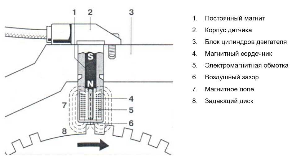
The principle of operation of the time sensor:
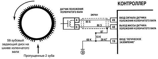
- The crankshaft is equipped with a disk with teeth (starting and zeroing). When the assembly rotates, the magnetic field is directed to the teeth from the PKV sensor, acting on it. Changes are recorded in the form of pulses and the information is transmitted to the computer: the position of the crankshaft is measured and the moment the pistons pass through the top and bottom dead centers (TDC and BDC) is recorded.
- When the sprocket passes the crankshaft speed sensor, it changes the type of boost reading. For this reason, the ECU is trying to restore the normal operation of the crankshaft.
- Based on the received pulses, the on-board computer sends a signal to the necessary vehicle systems.
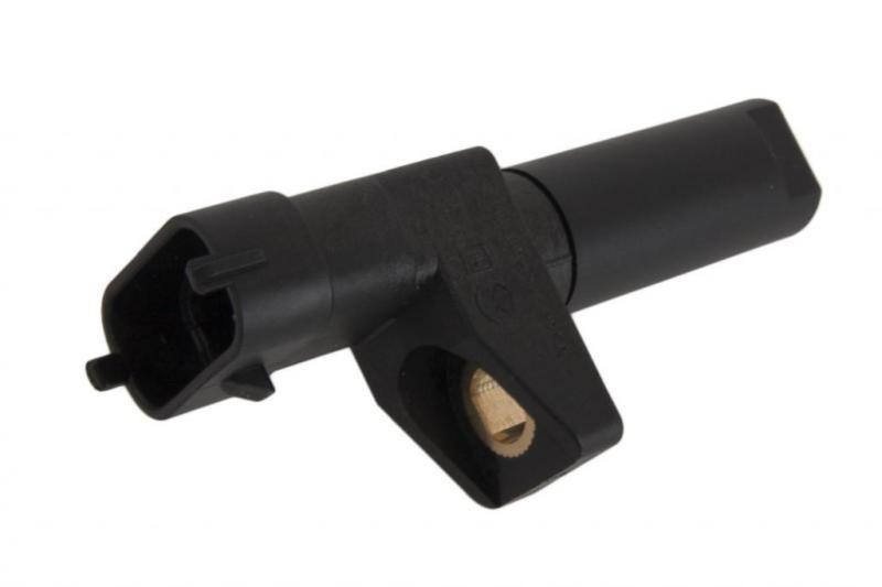
DPKV device
Crankshaft sensor design:
- an aluminum or plastic case with a cylindrical shape with a sensitive element, through which a signal is sent to the computer;
- communication cable (magnetic circuit);
- drive unit;
- sealant;
- winding;
- engine mount bracket.
Table: types of sensors
| First name | Description |
| Magnetic sensor
| The sensor consists of a permanent magnet and a central winding, and this type of controller does not require a separate power supply. An inductive electrical device controls not only the position of the crankshaft, but also the speed. It works with the voltage that occurs when a metal tooth (tag) passes through a magnetic field. This generates a signal pulse that goes to the ECU. |
| Optical sensor
| The optical sensor consists of a receiver and an LED. Interacting with the synchronizing disk, it blocks the optical flow passing between the receiver and the LED. The transmitter detects light interruptions. When the LED passes through the area with worn teeth, the receiver reacts to the pulse and performs synchronization with the ECU. |
| Hall Sensor
| The sensor design includes:
In a Hall effect crankshaft sensor, current flows as it approaches a changing magnetic field. The circuit of the force field opens when passing through areas with worn teeth and the signal is transmitted to the electronic engine control unit. Operates from an independent power source. |

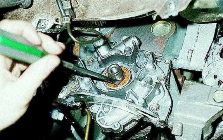
Where is the sensor located?
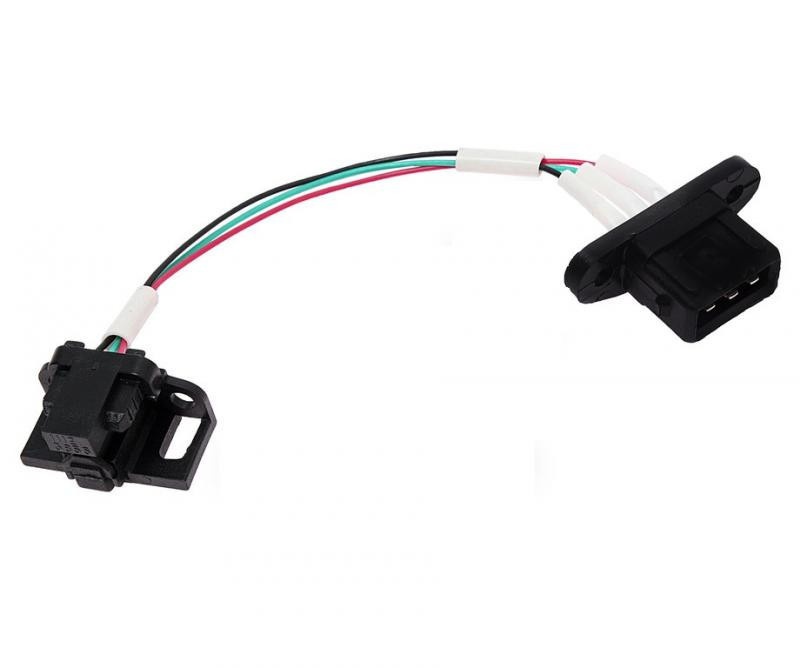
Location of the crankshaft position sensor: next to the disk between the alternator pulley and the flywheel. For free connection to the on-board network, a cable 50-70 cm long is provided, on which there are connectors for keys. There are spacers on the saddle to set the gap 1-1,5mm.
Symptoms and causes of malfunctions
Symptoms of a broken DPKV:
- the engine does not start or spontaneously stops after a while;
- no sparks;
- ICE detonation occurs periodically under dynamic loads;
- unstable idle speed;
- engine power and vehicle dynamics are reduced;
- when changing modes, a spontaneous change in the number of revolutions occurs;
- check the engine light on the dashboard.
Symptoms point to the following reasons why the PCV sensor may be faulty:
- short circuit between winding turns, possible distortion of the signal about the position of the piston at BDC and TDC;
- the cable connecting the DPKV to the ECU is damaged - the on-board computer does not receive proper notification;
- defect of teeth (scuffs, chips, cracks), the engine may not start;
- the ingress of foreign objects between the toothed pulley and the counter or damage while working in the engine compartment often causes a malfunction of the DPKV.
Problems with starting the engine
Variants of malfunctions of the crankshaft sensor that affect the operation of the internal combustion engine:
- The engine does not start. When the ignition key is turned, the starter turns the engine and the fuel pump hums. The reason is that the engine ECU, without receiving a signal from the crankshaft position sensor, cannot correctly issue a command: on which of the cylinders to start and on which to open the nozzle.
- The engine heats up to a certain temperature and stalls or does not start in severe frost. There is only one reason - a microcrack in the PKV sensor winding.
Unstable operation of the engine in various modes
This happens when the DPKV is contaminated, especially when metal chips or oil get into it. Even a slight impact on the magnetic microcircuit of the time sensor changes its operation, because the counter is very sensitive.
The presence of detonation of the motor with increasing load
The most common reason is the failure of the metering device, as well as a microcrack in the winding, which bends during vibration, or a crack in the housing, into which moisture enters.
Signs of engine knock:
- violation of the smoothness of the process of combustion of the fuel-air mixture in the cylinders of the internal combustion engine;
- jumping on the receiver or exhaust system;
- failure;
- a clear reduction in engine power.
Reduced engine power
Engine power drops when the fuel-air mixture is not supplied in time. The cause of the malfunction is the delamination of the shock absorber and the displacement of the toothed star relative to the pulley. Engine power is also reduced due to damage to the winding or housing of the crankshaft position meter.
How to check the crankshaft sensor yourself?
You can independently investigate the health of the DPKV using:
- ohmmeter;
- oscillograph;
- complex, using a multimeter, megohmmeter, network transformer.
It is important to know
Before replacing the measuring device, it is also recommended to carry out a complete computer diagnostics of the internal combustion engine. Then an external inspection is carried out, eliminating contamination or mechanical damage. And only after that they begin to diagnose with special devices.
Checking with an ohmmeter
Before proceeding with the diagnosis, turn off the engine and remove the timing sensor.
Step-by-step instructions for studying DPKV with an ohmmeter at home:
- Install an ohmmeter to measure resistance.
- Determine the degree of throttle resistance (touch the tester probes to the terminals and ring them).
- Acceptable value is from 500 to 700 ohms.
Using an oscilloscope
The crankshaft position sensor is checked with the engine running.
Algorithm of actions using an oscilloscope:
- Connect the tester to the timer.
- Run a program on the on-board computer that monitors readings from an electronic device.
- Pass a metal object in front of the crankshaft sensor several times.
- The multimeter is OK if the oscilloscope responds to movement. If there are no signals on the PC screen, it is recommended to carry out a full diagnosis.

Comprehensive check
To carry it out, you must have:
- megohmmeter;
- network transformer;
- inductance meter;
- voltmeter (preferably digital).
Algorithm of actions:
- Before starting a full scan, the sensor must be removed from the engine, thoroughly washed, dried, and then measured. It is carried out only at room temperature, so that the indicators are more accurate.
- First, the inductance of the sensor (inductive coil) is measured. Its operating range of numerical measurements should be between 200 and 400 MHz. If the value differs greatly from the specified value, it is likely that the sensor is faulty.
- Next, you need to measure the insulation resistance between the terminals of the coil. To do this, use a megaohmmeter, setting the output voltage to 500 V. It is better to carry out the measurement procedure 2-3 times to obtain more accurate data. The measured insulation resistance value must be at least 0,5 MΩ. Otherwise, insulation failure in the coil can be determined (including the possibility of a short circuit between turns). This indicates a device failure.
- Then, using a network transformer, the time disk is demagnetized.
Trouble-shooting
It makes sense to repair the sensor for such malfunctions as:
- penetration into the PKV pollution sensor;
- the presence of water in the sensor connector;
- rupture of the protective sheath of cables or sensor harnesses;
- change of polarity of signal cables;
- no connection with the harness;
- short signal wires to sensor ground;
- reduced or increased mounting clearance of the sensor and synchronizing disk.
Table: work with minor defects
| Default | Means |
|---|---|
| Penetration inside the PKV sensor and contamination |
|
| Presence of water in the sensor connector |
|
| Broken sensor cable shield or harness |
|
| Reverse the polarity of the signal cables |
|
| The sensor is not connected to the harness |
|
| Sensor signal wires shorted to ground |
|
| Reducing or increasing the mounting clearance of the sensor and the synchronizing disk |
|
How to change the crankshaft position sensor?
Important nuances that must be observed when replacing the DPKV:
- Before disassembly, it is necessary to apply marks indicating the position of the bolt relative to the sensor, the DPKV itself, as well as the marking of wires and electrical contacts.
- When removing and installing a new PKV sensor, it is recommended to make sure that the timing disk is in good condition.
- Replace meter with harness and firmware.
To replace the PKV sensor, you will need:
- new measuring device;
- automatic tester;
- cavernometer;
- wrench 10.
algorithm
To change the crankshaft position sensor with your own hands, you need:
- Switch off the ignition.
- De-energize the electronic device by disconnecting the terminal block from the controller.
- With a wrench, unscrew the screw fixing the sensor, remove the faulty DPKV.
- Use a rag to clean the landing site of oily deposits and dirt.
- Install the new pressure gauge using the old fasteners.
- Perform control measurements of the gap between the teeth of the alternator drive pulley and the sensor core using a vernier caliper. The space must correspond to the following values: 1,0 + 0,41 mm. If the gap is smaller (greater) than the specified value during the control measurement, the position of the sensor must be corrected.
- Check the resistance of the crankshaft position sensor using a self-test. For a working sensor, it should be in the range from 550 to 750 ohms.
- Reset the trip computer to turn off the Check Engine signal.
- Connect the crankshaft position sensor to the mains (a connector is installed for this).
- Check the performance of the electrical appliance in different modes: at rest and under dynamic load.