Electrical equipment of carburetor and injection VAZ 2104
Content
- Aggregate power supply schemes VAZ 2104
- Electrical wiring under the hood
- Switching in the cabin VAZ 2104
- Replacing wiring VAZ 2104
- The main malfunctions of electrical equipment VAZ 2104
VAZ 2104 with rear-wheel drive and station wagon body was produced from 1982 to 2012. The model was constantly improved: the electrical equipment changed, a fuel injection system, a five-speed gearbox and semi-sport front seats appeared. The VAZ 21043 modification was supplemented with a system for cleaning and heating the rear window window. The power supply system of individual vehicle components is quite simple.
Aggregate power supply schemes VAZ 2104
All VAZ 2104 systems that consume electricity are switched over a single-wire line. The sources of electricity are the battery and the generator. The positive contact of these sources is connected with electrical devices, and the negative one goes to the body (ground).
Electrical equipment VAZ 2104 is divided into three types:
- working equipment (battery, generator, ignition, starter);
- auxiliary operational equipment;
- light and sound signaling.
When the engine is off, all electrical equipment, including the starter, is powered by the battery. After starting the engine with a starter, the generator becomes the source of electricity. At the same time, it restores the battery charge. The ignition system creates a spark discharge to ignite the air-fuel mixture entering the engine. The functions of the light and sound alarm include external lighting, interior lighting, turning on the dimensions, giving an audible signal. Switching of electrical circuits occurs through the ignition switch, which consists of an electrical contact assembly and a mechanical anti-theft device.
The VAZ 2104 uses a 6ST-55P battery or similar. A synchronous generator 37.3701 (or G-222) is used as an alternating current source. This is a three-phase generator with electromagnetic excitation and a built-in silicon diode rectifier. The voltage removed from these diodes feeds the rotor winding and is fed to the battery charge control lamp. On vehicles with alternator 2105-3701010, this lamp is not activated, and the battery charge level is monitored by a voltmeter. The generator is mounted on brackets in the right (in the direction of travel) front of the engine compartment. The generator rotor is driven by the crankshaft pulley. Starter 35.3708 is attached to the clutch housing on the right side of the engine, protected by a heat-insulating shield from the exhaust pipe and is activated by an electromagnetic remote control relay.
The VAZ 2104 uses a contact, and in cars manufactured after 1987, a non-contact ignition system. The contact system contains the following elements:
- a distributor-breaker designed to open the circuit of the ignition coil with a low voltage current and distribute high voltage pulses to the spark plugs;
- ignition coil, the main function of which is to convert low voltage current into high voltage current;
- spark plug;
- high voltage wires;
- ignition switch.
The contactless system consists of:
- a distribution sensor that supplies low voltage control pulses to the switch and distributes high voltage pulses to the spark plugs;
- a switch designed to interrupt the current in the low voltage circuit of the ignition coil in accordance with the signals of the distribution sensor;
- ignition coils;
- spark plugs;
- high-voltage wires.
Current is constantly supplied to electrical circuits:
- sound signals;
- stop signals;
- cigarette lighter;
- interior lighting;
- portable lamp sockets;
- emergency light signaling.
For switching and protecting electrical appliances from voltage surges in a special niche in the engine compartment there is a mounting block with fuses and relays, the purpose of which is schematically indicated on the cover of the block. The standard unit can be removed, the board replaced, or its conductive paths restored.
On the dashboard of the VAZ 2104 there are power keys:
- external lighting fixtures;
- fog lights;
- heated rear window;
- interior heating.
The light alarm button is located on the protective casing of the steering column shaft, and under the column there are switches for the low and high beams, turn signals, wipers and windshield washer.
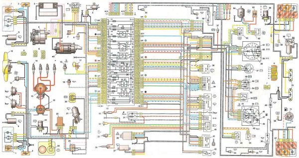
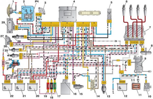
Wiring diagram VAZ 21043 and 21041i (injector)
Models VAZ 21043 and 21041i (sometimes incorrectly referred to as 21047) have identical power supply circuits. All electrical equipment of these cars is similar to the equipment of the VAZ 2107.
The export version of the VAZ 2104 and VAZ 21043 additionally includes a cleaner and heated rear window. Since 1994, this scheme has become the standard for all manufactured fours. After the appearance of injection models, the scheme was somewhat changed. This was also due to the appearance of a five-speed gearbox, electrical equipment and interior from the VAZ 2107, as well as electronic components that control the operation of the engine.
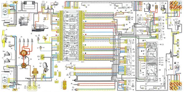
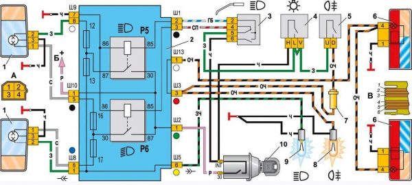
Wiring diagram VAZ 2104 (carburetor)
The distinctive features of the VAZ 2104 electrical equipment of the first years of production include:
- generator G-222;
- ten-pin alarm switch;
- five-pin relay for direction indicators and alarms;
- upper (dead) point sensor of the first cylinder;
- diagnostic block;
- rear window heating indicator lamp;
- a two-position switch for external lighting and a three-position light switch located under the steering column;
- absence of a control lamp for the air damper of the carburetor.
Electrical wiring under the hood
VAZ 2104 as standard is similar to the VAZ 2105 model. The changes affected only:
- dashboard;
- rear blocks of marker lights and brake lights;
- fuel supply schemes in a car with an injector.
Features of the engine compartment wiring of cars with an injector are displayed on the VAZ 2104 power supply diagrams.
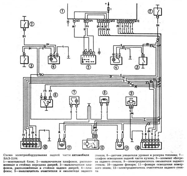
Switching in the cabin VAZ 2104
In relation to the schemes taken as a basis from the VAZ 2105 and 2107, the electrical equipment of the VAZ 2104 and 21043 cabin has been supplemented:
- rear window cleaner, which is activated by a button on the dashboard;
- dome light for the rear of the body.
The rear window cleaner consists of a gearmotor, a lever and a brush. The gearmotor, as well as the windshield washer motor, can be disassembled. The electrical circuit of the cleaner and washer is protected by fuse No. 1, and the circuit of the ceiling lamp is protected by fuse No. 11. Power is supplied to the backlight, defroster and rear window wiper via a wiring harness.
Replacing wiring VAZ 2104
In the event of a power outage to electrical equipment, the first thing to check is the integrity of the electrical circuit. For this you need:
- Disconnect the area under test by disconnecting the negative battery terminal or the appropriate fuse.
- Connect the multimeter contacts to the ends of the problematic section of the circuit, and one of the probes to ground.
- If there is no indication on the multimeter display, there is an open in the circuit.
- Wiring is replaced with a new one.
The selection of wires and the replacement of wiring is carried out according to the VAZ 2104 power supply scheme. In this case, standard components or components from another model with suitable characteristics are used.
Video: replacing wiring, fuses and relays of classic VAZ models

To replace the wiring, the front of the cabin is disassembled. Wires of insufficient length are extended, and the connections are soldered and insulated.
Video: replacing wiring in the cabin and under the hood

It is almost impossible to completely replace the wiring of the VAZ 2104 with your own hands. In such a situation, it is better to contact a car service.
Video: repair of the wiring of the injection VAZ 2107

The main malfunctions of electrical equipment VAZ 2104
The main faults in the wiring are short circuits and broken wires. When shorted, fuses blow, relays and devices fail. Sometimes even a fire can occur. When a wire breaks, the nodes to which this wire is connected stop working.
Mounting block
All electrical equipment is connected through fuses located in the mounting block and providing protection for this equipment in case of a short circuit. Mounting blocks manufactured in the Russian Federation or Slovenia are installed on the VAZ 2104. The latter are not disassembled and cannot be repaired.
Table: fuses in the VAZ 2104 mounting block
| Fuse (rated current) | Protected circuit equipment |
| 1 (8A) | Rear reversing lights; Heater motor; Warning lamp, rear door glass heating relay. |
| 2 (8A) | Windshield wiper and washer motors; Electric motors for cleaners and headlight washers; Windshield wiper relay. Relay cleaners and headlight washers (contacts). |
| 3 (8A) | Spare. |
| 4 (8A) | Spare. |
| 5 (16A) | Heating element and relay for turning on the heating of the rear door glass. |
| 6 (8A) | Cigarette lighter; Socket for portable lamp; Clock; Lights signaling open front doors. |
| 7 (16A) | Sound signals and relays for switching on signals; The electric motor of the fan of the engine cooling system and the relay for turning on the electric motor (contacts). |
| 8 (8A) | Switch and relay-interrupter of direction indicators in alarm mode. |
| 9 (8A) | Generator voltage regulator (on vehicles with a GB222 generator). |
| 10 (8A) | Direction indicators when turned on and the corresponding control lamp; Relay for turning on the fan motor (winding); Control devices; Control lamp of a charge of the accumulator; Control lamps for fuel reserve, oil pressure, parking brake and brake fluid level; The relay-interrupter of a control lamp of a parking brake; Carburetor solenoid valve control system. |
| 11 (8A) | Rear brake lights; Interior lighting fixture. |
| 12 (8A) | Right headlight (high beam); Winding of the relay for switching on the headlight cleaners (when the high beam is on). |
| 13 (8A) | Left headlight (high beam); Control lamp for turning on the high beam headlights. |
| 14 (8A) | Left headlight (side light); Right rear light (side light); License plate lights; Engine compartment lamp; A control lamp of inclusion of dimensional light. |
| 15 (8A) | Right headlight (side light 2105); Left rear light (side light); Cigarette lighter illumination; Illumination of devices; Glove box lighting. |
| 16 (8A) | Right headlight (dipped beam); Winding of the relay for switching on the headlight cleaners (when the dipped beam is on). |
| 17 (8A) | Left headlight (low beam 2107). |
Connections of the mounting block VAZ 2104
In addition to the fuses, there are six relays in the mounting block.
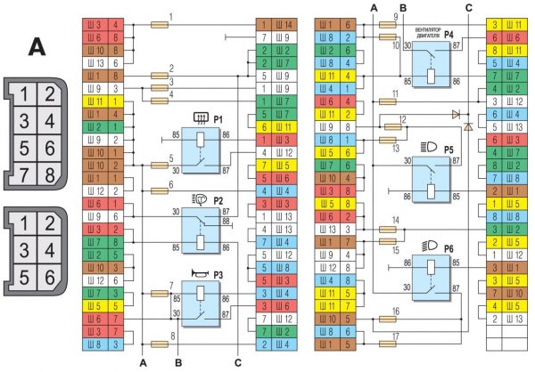
In addition, in the figure:
- the numbers under the letter A correspond to the plug number in the blocks of the mounting block;
- the numbers next to the letter Ш indicate the number of the block and the number of the plug;
- socket plugs without color marking are marked in brown.
Video: repair of the fuse box of classic VAZ models

When replacing fuses and repairing the mounting block, you must:
- disconnect the negative terminal of the battery with the ignition off;
- when replacing a fuse, identify the cause of its blown;
- do not use oversized fuses to avoid burning out the corresponding board tracks.
Video: restoration of the tracks of the mounting block VAZ 2105

Connecting low, high and fog light
The scheme for switching on headlights and fog lights in the rear lights of the VAZ 2104 is similar to the corresponding schemes for the VAZ 2105 and VAZ 2107.
Fuel supply system
The distributed injection system in the injection VAZ 2104 involves the supply of fuel to each cylinder by a separate nozzle. This system combines power and ignition subsystems controlled by the January-5.1.3 controller.
The controller, which receives information about the parameters of the engine, identifies all faults and, if necessary, sends a Check Engine signal. The controller itself is mounted on a bracket in the cabin behind the glove box.
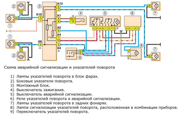
Switches located on the steering column
The direction indicator switches are located under the steering column, and the alarm button is on the column itself. The flashing of the direction indicators at a frequency of 90 ± 30 times per minute provides an alarm relay at a voltage of 10,8–15,0 V. If one of the direction indicators fails, the blinking frequency of the other indicator and the control lamp doubles.
Electric windows
Some car owners install power windows on their VAZ 2104.
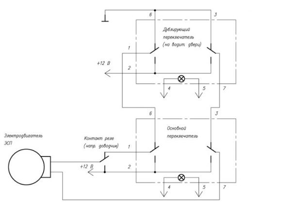
The installation features of such power windows on the VAZ 2104 are determined by the size and design of the front door windows. Unlike other classic VAZ models, the front doors of the four (like the VAZ 2105 and 2107) do not have rotary windows. Fully lowered front windows take up more space inside the door body.
Video: installation on the front doors of the VAZ 2107 window lifters "Forward"

When choosing power windows, you should provide for the presence of free space for installing an electric motor and a drive mechanism.
Video: installation on the VAZ 2107 window lifters "Garnet"

Thus, an independent repair of the VAZ 2104 electrical equipment for an inexperienced car owner is usually limited to replacing fuses, relays and warning lights, as well as searching for a broken electrical wiring. To do this, having in front of your eyes the wiring diagrams for electrical appliances, is quite simple.

