Hydraulic booster MAZ
Adjustment of the clearance of the ball joint of the hydraulic booster MAZ.
The appearance of gaps in the ball pins significantly affects the overall play of the headset. Very often, the gap in the ball pin 9 increases (see Fig. 94), to which the longitudinal rod is connected, since much more force is transmitted through this ball pin than through the ball pin of the steering lever.
To adjust the gaps of the ball pins, the hydraulic booster is partially disassembled. Therefore, it is better to carry out the adjustment on the hydraulic booster removed from the car.
The setup procedure is as follows.
Drag joint gap adjustment:
- remove pipes;
- clamp the hydraulic booster in a vise and loosen the lock nut on the cylinder;
- unscrew the hinge body from the cylinder;
- fix the hinge bodies in a vice, loosen the locking screw on the nut 7 (see Fig. 94);
- tighten the nut 7 until it stops, then tighten the lock screw tightly;
- Assemble the body of balls with the cylinder. Tighten as far as it will go and unscrew to a position that allows the pipes to be connected.
Pivot joint play adjustment:
- fix the hydraulic booster in a vice;
- remove cover 12 from the distributor, unscrew and unscrew the nut;
- unscrew the screws holding the coil housing and remove the housing together with the coil;
- unscrew the locking screw 29;
- screw the cap 29 all the way and turn it back until the hole for the locking screw aligns with the nearest slot in the cup 36;
- tighten the locking screw until it stops;
- install and secure the coil body;
- insert the spool into the body sleeve, put on cap 32, tighten the nut until it stops, unscrew it by 1/12 turn and cut the thread;
- install and secure cover 12 and pipes;
- install the hydraulic booster on the car.
Possible control malfunctions and ways to eliminate them are given on the eleventh tab.
| Cause of failure | Resource |
| Insufficient or uneven amplification | |
| Insufficient tension of the pump drive belt | Adjust belt tension |
| Low oil level in the power steering pump reservoir | Add oil |
| Oil foam in the tank, presence of air in the hydraulic system | Remove air from the system. If air does not bleed, check all connections for leaks. |
| Complete lack of gain at various engine speeds | |
| Blockage of the pressure and drain pipeline of the hydraulic system | Dismantle the lines and check the patency of the pipes and hoses included in them |
| No momentum when turning to one side | |
| Seizure of the power steering distributor spool | Disassemble the distributor, find and eliminate the cause of jamming |
| Jamming of the spherical cup of the finger of the hydraulic servomotor | Disassemble the hydraulic booster and eliminate the cause of the cup jamming |
| Backlash in the connection of the spool with the glass of the ball pin of the steering lever | Remove the front cover of the distributor, eliminate the play by tightening the nut until the gap between the nut and the spool is selected, then the cotter pin |
MAZ hydraulic booster repair
Removing the hydraulic booster from the car. To remove it you need:
- disconnect the pressure and drain hoses from the hydraulic booster;
- unscrew the nut of the coupling bolt holding the pin on the head of the hydraulic servomotor rod, and knock the bolt out of the bracket;
- hit the stud of the head of the hydraulic booster rod;
- unscrew and unscrew the nuts securing the hydraulic booster to the steering lever and to the trailing arm;
- using a punch, press your fingers out of the holes in the steering arm and trailing link. Remove the hydraulic booster. The procedure for disassembling the hydraulic booster is as follows: remove the pipes and fittings;
- loosen the threaded connection of the stem head with the stem and unscrew the head. Remove the outer fixing washer; lid;
- when the rubber bushing is worn, disassemble the head, for which unscrew the nut and press out the steel bushing, and then the rubber bushing;
- remove the clamp holding the cover, cover and inner washer from the mount;
- unscrew the screws holding the power steering cylinder cover, remove the washer, remove the retaining ring by sliding the cylinder cover back, remove the cover;
- remove the piston with the rod and disassemble it;
- unscrew the lock nut of the cylinder and turn the cylinder out;
- remove the clamps securing the ball joint seals and the seals themselves;
- unscrew the locking screw, unscrew the adjusting nut 7 (see Fig. 94), remove the pusher 8, spring, crackers and ball pin 9;
- unscrew the cover fastening screws 12 and remove the cover; unscrew the coil fastening nut and unscrew it, remove the cap 32;
- unscrew the screws that hold the coil body, take out the body, take out the coil;
- unscrew the locking screw, unscrew the plug 29, remove the bolt, pusher 8, spring, crackers and pin 10;
- remove glass 36;
- unscrew the check valve cap 35 and remove the ball spring i.
After disassembly, carefully inspect the parts of the hydraulic booster.
Scratches and nicks are not allowed on the surfaces of the spool, the glass of the steering lever ball pin and their bodies. The running surfaces of the ball studs and rocker must be free of dents and excessive wear, and the rubber rings must show visible damage and wear.
If any damage is found, replace these parts with new ones.
Install the hydraulic booster in the reverse order of removal. Before assembly, the rubbing surfaces of the coil, glass and fingers; lubricate with a thin layer of lubricant and make sure that the coil and cup move freely in their housings, without interference.
Adjust the ball joint clearance as described above.
After assembly, lubricate the ball bearings with grease through an oiler 18.
Install the hydraulic booster on the car in the reverse order of removal.
When installing the hydraulic booster, tighten the nuts securing the pins tightly and screw them carefully.
Maintenance of hydraulic booster MAZ
During the operation of the car, systematically check the fastening of the hydraulic booster to the bracket of the car frame, the fastening of the hydraulic booster pump pulley, periodically tighten the nuts of the distributor ball studs.
Check the tension of the pump drive belt at every maintenance. Belt tension is adjusted by screw 15 (Fig. 96, b). With the correct tension, the deflection in the middle of the belt under a force of 4 kg should be within 10-15 mm. After adjustment, lock the screw with nut 16.
Read also 8350 and 9370 Trailer Maintenance
Periodically, at the time indicated in the lubrication chart, check the oil level in the hydraulic booster pump reservoir, change the oil in the hydraulic booster system, and wash the reservoir filter.
Daily check the tightness of the connections and seals of the hydraulic booster, pump, pipes and hoses of the system.
For the power steering system, use only clean, filtered oil as specified on the lubrication chart. Pour oil into the pump reservoir 10-15 mm below the upper edge of the reservoir through a funnel with a double fine mesh. When pouring oil, do not shake or stir it in the container.
The use of contaminated oil leads to rapid wear of the power steering cylinder, distributor and pump parts.
When checking the oil level in the pump reservoir at each maintenance (TO-1), the front wheels of the car must be installed straight.
At each TO-2, remove the filter from the tank and rinse. If the filter is heavily clogged with hardened deposits, wash it with a car paint thinner. Before removing the filter, thoroughly clean the lid of the debris tank.
When changing the oil, which is carried out 2 times a year (with seasonal maintenance), raise the front axle of the car so that the wheels do not touch the ground.
To drain oil from the system:
- disconnect the tank and, having removed the cover, drain the oil;
- disconnect the nozzles from the discharge and drain pipelines of the distributor and drain the oil from the pump through them;
- slowly turning the flywheel to the left and right until it stops, drain the oil from the power cylinder.
After draining the oil, flush the power steering reservoir:
- remove the filter from the tank, wash it as described above;
- thoroughly clean the tank from the inside, removing traces of contaminated oil;
- install the washed filter in the tank;
- pour fresh oil into the tank through a funnel with a double fine mesh and wait until it drains through the nozzles.
When filling in new oil, be sure to completely remove air from the system. For this you need:
- add oil to the tank to the desired level and do not touch the system for about two minutes;
- start the engine and let it run at low speed for two minutes;
- slowly turn the steering wheel 2 times all the way to the right and left until the air bubbles in the reservoir stop. If necessary, add oil to the level indicated above; reinstall the tank cover and its fasteners;
- turn the wheels to the right and left, checking for ease of control and for oil leaks.
Check the clearances of the ball pins with the engine running on each TO-1, sharply turning the steering wheel clockwise and counterclockwise.
There must be no play in the tie rod joint. In the hinge of the steering lever with the engine stopped, the play should not exceed 4 mm, and with the engine running - up to 2 mm.
The device and operation of the hydraulic booster
The hydraulic booster (Fig. 94) is a unit consisting of a distributor and a power cylinder assembly. The hydraulic system of the booster includes an NSh-10E gear pump mounted on a car engine, an oil tank and pipelines.
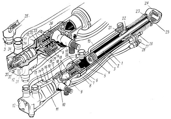
Rice. 94. GUR MAZ:
1 - power cylinder; 2 - rods; 3 - discharge pipe; 4 - piston; 5 - cork; 6 - body of ball bearings; 7 - adjustment of the backlash of the nut of the longitudinally-stop ball joint; 8 - pusher; 9 — a ball pin of longitudinal draft; 10 - tie rod ball pin; 11 - drain pipe; 12 - cover; 13 - distributor housing; 14 - flange; 15 - branch pipe into the cavity above the piston of the power cylinder; 16 — a collar of fastening of a sealant; 17 - branch pipe into the cavity of the piston of the power cylinder; 18 - oiler; 19 - pins for fixing crackers; 20 - locking screw; 21 - power cylinder cover; 22 - screw; 23 - inner washer for fastening the cover; 24 - thrust head; 25 - cotter pin; 26 - fastening of the drain line; 27 - assembly of the discharge line; 28 - hose holder; 29 - adjust the set of heads of the ball joint of the steering arm; 30 - coil; 31 - cork; 32 - spool cap; 33 - coupling bolt; 34 - connecting channel; 35 - check valve; 36 - glass
The distributor consists of a body 13 and a spool 30. The spool bushings are sealed with rubber sealing rings, one directly in the body, the other in a plug 32 inserted into the body and closed with a cap 12.
There are three annular grooves on the inner surface of the coil body. The extreme ones are connected by a channel to each other and to the discharge line of the pump, the middle ones - through the drain line to the pump tank. On the surface of the drum there are two annular grooves connected by connecting channels 34 with closed volumes called reactive chambers.
The coil body is attached to the body flange with 6 hinges. There are two ball pins in housing 6: 10, to which the steering rod is attached, and 9, connected to the longitudinal steering rod. Both fingers are held between the spherical biscuits by a plug 29 and an adjusting nut 7 by means of springs. The tightening of the biscuits is limited by pushers 8. The hinges are protected from dirt by rubber seals fixed to the body with clamps.
The fingers within certain limits can rotate in the biscuits, which are held by broken pins 19, which are included in the grooves of the biscuits.
Read also Technical characteristics of the brake system of trailers GKB-8350, OdAZ-9370, OdAZ-9770
A bipod 36 is fixed in the cup 10, which can move in the housing 6 in the axial direction within 4 mm. This movement is limited by a cork collar 29 wrapped in a glass. Shoulder in the extreme positions rests against the end of the housing 13 of the distributor and against the end of the body 6 of the ball bearings. The spool 30 also moves with the cup 36, as it is rigidly connected to it by means of a bolt and nut.
The power cylinder 1 is connected to the other end of the hinge body 6 by means of a threaded connection and is locked with a nut. Piston 4 moves in the cylinder, connected by a nut to rod 2. The piston is sealed with two cast iron rings. The cylinder cavity is closed on one side with a plug 5, sealed with a rubber ring, on the other, with a cover 21, sealed with the same ring and secured with a retaining ring and a washer, to which the cover is bolted. The stem is sealed in the cover with a rubber ring protected by a scraper. Outside, the stem is protected from contamination by a corrugated rubber boot. At the end of the rod, a head 24 is fixed with a threaded connection, in which rubber and steel bushings are placed.
The rubber bushing is fixed at the ends with a steel collar of the bushing and a nut. The cavity of the power cylinder is divided by the piston into two parts: under-piston and over-piston. These cavities are connected by branch pipes 15 and 17 with channels in the distributor body, ending with channels opening into the body cavity between the annular grooves.
The cavities under and above the piston of the power cylinder can be interconnected through the check valve 35, which consists of a ball and a spring pressed by a plug.
The hydraulic booster works as follows (Fig. 95). When the car engine is running, the pump 11 continuously supplies oil to the hydraulic booster 14, which, depending on the direction of the car, returns to the tank 10 or is fed into one of the working cavities (A or B) of the power cylinder 8 through pipes 5 and 6. Another cavity when connected through drain line 12 with tank 10.
The oil pressure through the channels 3 in the spool 2 is always transmitted to the reactive chambers 1 and tends to move the spool to a neutral position with respect to the body.
When the vehicle is in a straight line (Fig. 95, a), the pump supplies oil through the discharge hose 13 to the extreme annular cavities 20 of the distributor, and from there through the gaps between the edges of the grooves of the spool and the housing - to the central annular cavity 21 and then along the drain line 12 to the tank 10 .
When the steering wheel is turned to the left (Fig. 95, b) and to the right (Fig. 95, c), the steering lever 19 through the ball pin 18 removes the spool from the neutral position and the drain cavity 21 in the spool body diverge, and the liquid begins to flow into the corresponding cavity of the power cylinder , moving the cylinder 8 relative to the piston 7, fixed on the rod 15. The movement of the cylinder is transmitted to the steered wheels through the ball pin 17 and the longitudinal steering rod XNUMX associated with it.
If you stop rotating the flywheel 9, the coil stops and the body moves towards it, moving to the neutral position. The oil begins to drain into the tank and the wheels stop turning.
The hydraulic booster has high sensitivity. To turn the wheels of the car, it is necessary to move the spool by 0,4-0,6 mm.
With an increase in resistance to turning the wheels, the oil pressure in the working cavity of the power cylinder also increases. This pressure is transferred to the reaction chambers and tends to move the spool to the neutral position.
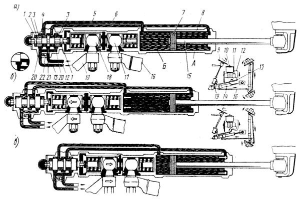
Rice. 95. Scheme of work GUR MAZ:
1 - reactive chamber; 2 - coil; 3 - channels; 4 - distributor housing; 5 and 6 - pipes; 7 - piston; 8 - power cylinder; 9 - steering wheel; 10 - tank; 11 - bomb; 12 - drain pipeline; 13 - pressure hose; 14 - hydraulic booster; 15 - piston rod; 16 - longitudinal thrust; 17 and 18 - ball fingers; 19 — steering lever; 20 - pressure cavity; 21 - drainage cavity; 22 - check valve
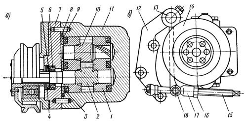
Rice. 96. Power steering pump MAZ:
bomb; b - tension device; 1 - right sleeve; 2 - driven gear; 3 - sealing ring; 4 - retaining ring; 5 - support ring; 6 - sleeve; 7 - cover; 8 - sealing ring; 9 - drive gear; 10 - left sleeve; 11 - pump housing; 12 - fixed support; 13 - axis; 14 - pulley; 15 - adjusting screw; 16 - locknut; 17 - fork; 18 - finger
Due to the amplifying effect of the hydraulic booster, the force on the steering wheel at the beginning of the turn of the wheels does not exceed 5 kg, and the maximum force is about 20 kg.
The hydraulic booster system has a safety valve installed on the power cylinder. The valve is set at the factory for a system pressure of 80-90 kg/cm2. Valve adjustment is prohibited in fleets.
It should be borne in mind that only short-term operation of the steering is allowed when the amplifier is not working, as this significantly increases the force on the steering wheel and increases its free play. The idle speed of the vehicle must not exceed 20 km/h.
The NSh-10E power steering gear pump (Fig. 96) is installed on the left side of the engine and is driven from the engine crankshaft using a V-belt. The working fluid reservoir is mounted on the radiator frame.