A Comprehensive Guide to the World of K-151 Series Carburettors
Content
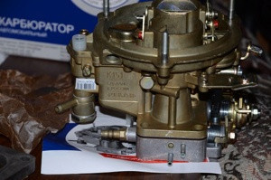
The K-151 carburetor of the Pekar plant (the former Leningrad carburetor plant) is designed for installation on four-cylinder automobile engines YuMZ and ZMZ, as well as on UZAM.
Different modifications of the carburetor differed in a set of jets and, accordingly, letter designations. The article will consider in detail the device "151st", its configuration and elimination of all kinds of malfunctions.
Device and principle of operation, diagram
The carburetor is designed for high-precision dosing of the air-fuel mixture and its subsequent supply to the engine cylinders.
The K-151 carburetor has 2 parallel channels through which purified air passes from the filter. Each of them has a rotary throttle (damper). Thanks to this design, the carburetor is called a two-chamber. And the throttle actuator is designed in such a way that, depending on how hard the accelerator pedal is pressed (that is, changes in the operating modes of the internal combustion engine), the first damper opens in due time, and then the second.
In the middle of each air channel there are cone-shaped constrictions (diffusers). Air passes through them, so the fuel is sucked through the jets of the float chamber.
In addition, the carburetor contains the following components:
- floating mechanism. It is designed to maintain a constant fuel level in the float chamber.
- The main dosing systems of the primary and secondary chambers. Designed for preparation and dosing of the air-fuel mixture for engine operation in various modes.
- The system is idle. It is designed to run the engine at a stable minimum speed. It consists of specially selected nozzles and air channels.
- transition system. Thanks to this, the additional camera is smoothly switched on. Operates in a transitional mode between idle and high engine speeds (when the throttle is less than half open).
- Boot device. It is intended for the facilitated start of the engine in a cold season. By pulling the suction rod, we turn the air damper into the primary chamber. Thus, the channel is blocked and the necessary vacuum is created for the re-enrichment of the mixture. In this case, the throttle valve opens slightly.
- Accelerator pump. A fuel supply device that compensates for the supply of a combustible mixture to the cylinders when the throttle is suddenly opened (when air flows faster than the mixture).
- Ecostat. Dosing system of the secondary mixing chamber. This is a nozzle through which additional fuel is supplied to the chamber at wide open throttle (when the air flow in the diffuser is maximum). This eliminates the lean mixture at high engine speeds.
- Economizer valve (EPKhH). Responsible for turning off the fuel supply to the carburetor in forced idle (PHX) mode. Its necessity is associated with a sharp increase in CO (carbon oxides) in the exhaust gases when the car is braked by the engine. Which negatively affects the operation of the engine.
- Forced crankcase ventilation system. Through it, toxic gases from the crankcase do not enter the atmosphere, but into the air filter. From there, they enter the carburetor with purified air for subsequent mixing with fuel. But the system is not idle because there are not enough vacuum parameters for suction. Therefore, a small additional branch was invented. It connects the crankcase outlet to the space behind the carburetor throttle, where maximum vacuum is applied.
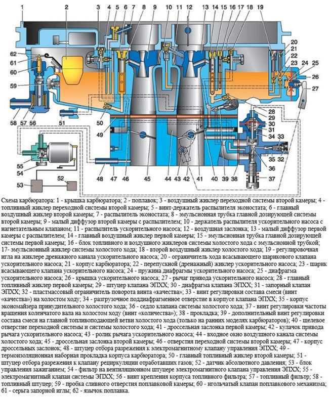
Below is a detailed diagram of the K-151 carburetor with symbols:
How to set up with your own hands
To adjust the K-151 carburetor, you will need the following minimum set of tools:
- flat and Phillips screwdrivers;
- the rule;
- cavernometer;
- adjusting and drilling probes (d= 6 mm);
- pump for tires
To remove the carburetor, you will need open-end wrenches or box wrenches in sizes 7, 8, 10 and 13.
Before tuning, remove the upper part of the carburetor, clean it of dirt and soot. At this stage, you can check the fuel level in the float chamber. This will be discussed in detail below.
Remove the carburetor only if absolutely necessary! Blowing with compressed air and flushing do not eliminate the consequences of clogging of the gates and contamination of the jets (channels).
It is important to understand that a not too dirty carb works just as well as a perfectly clean one. Moving parts are self-cleaning, dirt does not get inside. Therefore, it is often necessary to clean the carburetor from the outside, in places where large particles of dirt stick to mutually moving parts (in the lever mechanism and in the starting system).
We will consider a partial disassembly of the device with all adjustments and subsequent assembly.
Removal and disassembly algorithm
Step-by-step algorithm for removing and disassembling the K-151 carburetor:
- open the car hood and remove the air filter housing. To do this, unscrew and remove the top bracket, and then the filter element. With a 10 key, unscrew the 3 nuts that hold the filter housing and remove it;
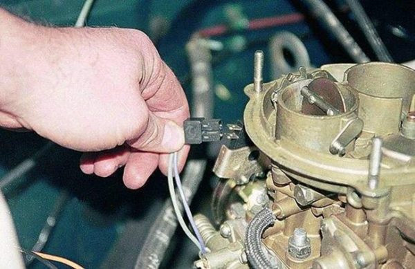
- pull out the plug from the EPHX microswitch;
- having disconnected all hoses and rods, with a key of 13 we unscrew 4 nuts that attach the carburetor to the manifold. Now we remove the carburetor itself. Important! It is better to mark the hoses and connections before removing them, so that nothing gets mixed up during their assembly;
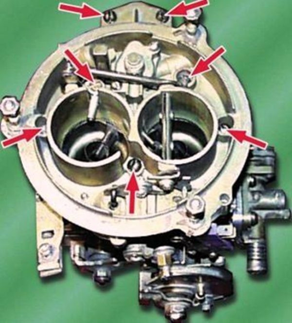
- take the carburetor off. We unscrew 7 fixing screws with a screwdriver and remove the top cover, not forgetting to disconnect the air damper drive rod from the lever;
- wash the carburetor with a special cleaning agent. For these purposes, gasoline or kerosene is also suitable. The nozzles are blown with compressed air. We check the integrity of the gaskets, if necessary, change them to new ones from the repair kit. Attention! Do not wash the carburetor with strong solvents, as this may damage the diaphragm and rubber seals;
- when disassembling the carburetor, you can adjust the starting device. If it does not work properly, it will be difficult to start the engine in cold weather. We'll talk about this setting later;
- screw the carburetor together with the top cap. We connect the block of microswitches and all the necessary wires.
If you suddenly forgot which hose to stick where, we suggest using the following scheme (for the ZMZ-402 engine):
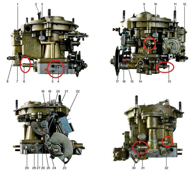
4- fitting for vacuum suction in the vacuum ignition timing controller (VROS); 5-vacuum suction fitting to the EPHH valve; 6 - crankcase gas intake fitting; 9-nipple selection of vacuum to the EGR valve; 13 - fitting for supplying vacuum to the EPCHG system; 30 channels for fuel extraction; 32 - fuel supply channel.
For the ZMZ 406 engine, a special K-151D carburetor is provided, in which there is no fitting number 4. The distributor function is performed by an electronic automatic pressure sensor (DAP), which is connected by a hose to the intake manifold, where it reads the vacuum parameters from the carburetor. Otherwise, connecting the hoses on the 406 engine is no different from the diagram above.
How to adjust float chamber fuel level
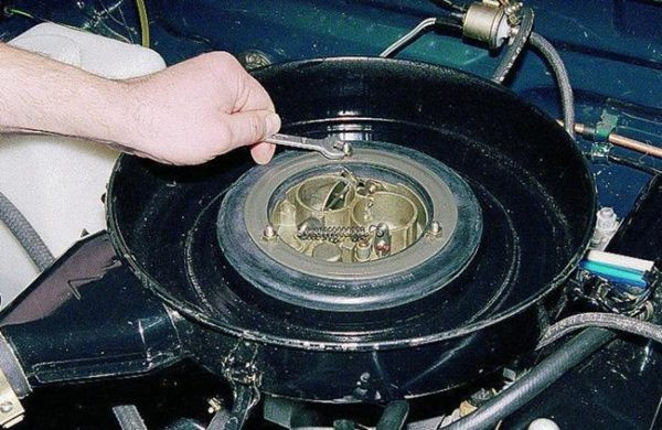
The normal fuel level for K-151 carburetors should be 215mm. Before measuring, we pump the required amount of gasoline into the chamber using the hand pump lever.
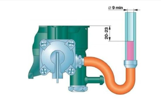
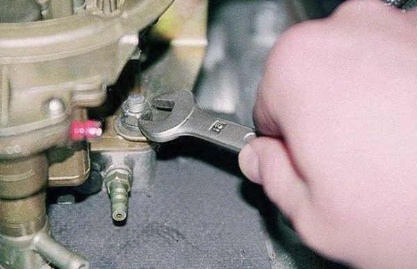
The level can be checked without removing the top of the carburetor (see picture above). Instead of the drain plug of the float chamber, a fitting with an M10 × 1 thread is screwed on, a transparent hose with a diameter of at least 9 mm is connected to it.
If the level is not correct, unscrew the carburetor cap to gain access to the float chamber. As soon as you remove the upper part, immediately measure the level with a depth gauge (from the upper plane of the carburetor to the fuel line). The fact is that gasoline evaporates quickly when dealing with the atmosphere, especially in hot weather.
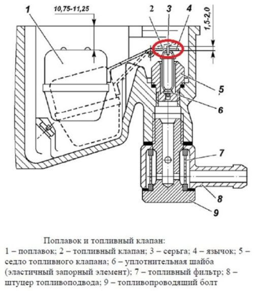
An alternative level control option is to measure the distance from the top plane of the chamber connector to the float itself. It should be within 10,75-11,25 mm. In case of deviation from this parameter, it is necessary to carefully bend the tongue (4) in one direction or another. After each bending of the tongue, gasoline must be drained from the chamber, and then refilled. Thus, fuel level measurements will be most accurate.
An important condition for the operation of the fuel level control system is the integrity of the rubber sealing ring (6) on the lock needle, as well as the tightness of the float.
Trigger adjustment
Before you start setting up a boot device, you should carefully familiarize yourself with your device and circuit.
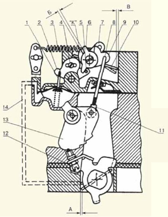
Algorithm of adjustment:
- While turning the throttle lever, simultaneously move the choke lever (13) as far as it will go to the leftmost position. We fix with a rope or wire. With the help of adjusting probes, we measure the gap between the throttle and the chamber wall (A). It should be in the range of 1,5-1,8 mm. If the gap does not correspond to the norm, we loosen the lock nut with a key to “8” and with a screwdriver, turning the screw, set the desired gap.
- We proceed to adjust the length of the rod (8). Links the trigger control cam and choke control lever. When unscrewing the threaded head 11 (in the first versions of the carburetor), the gap (B) between the levers 9 and 6 is set equal to 0,2-0,8 mm.
- In this case, lever 6 must touch the antennas 5. If not, unscrew the screw and turn the lever 6 to the left until it stops with the antennas of the two-arm lever (5). On late model carburetors, gap (B) is set by unscrewing the screw that secures the shoe to cam 13 and moving it up with the stem, and then tightening the screw.
- Finally, check the gap (B). Having sunk rod 1, insert a 6 mm drill into the resulting gap (B) (deviations of ± 1 mm are allowed). If it does not enter the hole or is too small for it, by unscrewing screw 4 and moving the two-arm lever, we achieve the required clearance.
A visual video on setting up a starter for a carburetor of the new K-151 model:
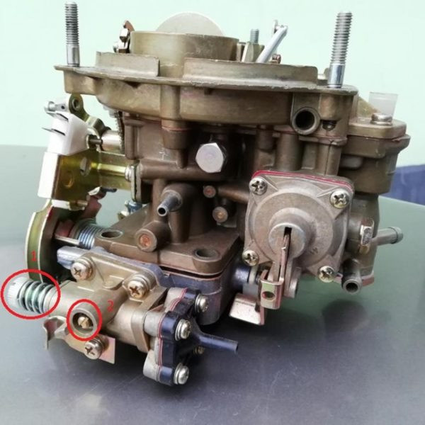
Setting the idle system
Idling adjustment is carried out to ensure stable operation of the engine with a minimum content of harmful carbon oxides (CO) in the exhaust gases. But since not everyone has a gas analyzer available, the tachometer can also be adjusted, depending on your own feelings from the engine.
To begin with, we start the engine and warm it up (the screw of quantity 1 is screwed into an arbitrary position). Remove the quality screw shank plug 2, if present.
Important! The choke must be open during idle adjustment.
After warming up with the quality screw, we find the position at which the engine speed will be maximum (a little more and the engine will stall).
Next, using the amount screw, increase the speed by about 100-120 rpm above the idle speed in the factory instructions.
After that, the quality screw is tightened until the speed drops to 100-120 rpm, that is, to the specified factory standard. This completes the idle adjustment. It is convenient to control measurements using a remote electronic tachometer.
When using a gas analyzer, the control (CO) in the exhaust gases should not exceed 1,5%.
We present to your attention an interesting, and most importantly useful video, with which it is easy to adjust the idle speed on the carburetor of any modification of the K-151:
Faults and their removal
Freezing of the economizer housing
The K-151 carburetor on some engines has an unpleasant feature. In negative wet weather, the fuel mixture in the carburetor actively condenses on its walls. This is due to the high vacuum in the channels at idle (the mixture moves very quickly, which causes a drop in temperature and the formation of ice). First of all, the economizer body freezes, since air enters the carburetor from here, and the passage section of the channels here is the narrowest.
In this case, only supplying hot air to the air filter can help.
The barrel of the air intake hose can be thrown directly into the manifold. Or make a so-called "brazier" - a heat shield made of a metal plate, which is located on the exhaust pipes and to which the air ventilation hose is connected (see Fig.).
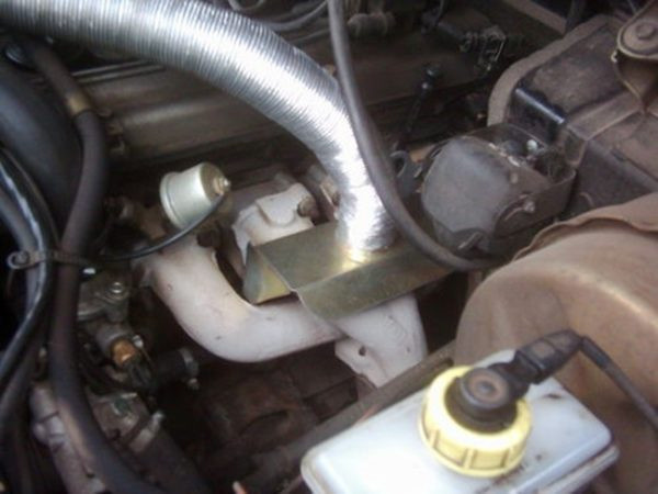
Also, to reduce the risk of an economizer freezing problem, we warmed up the engine to an operating temperature of 60 degrees before the trip. Despite the insulating gasket on the engine, the carburetor still receives some heat.
Flange dressing
With frequent disassembly and removal of the carburetor, as well as with excessive force when tightening the flange to the engine, its plane may be deformed.
Working with a damaged flange causes air leakage, fuel leakage and other serious consequences.
There are many ways to solve this problem. But the simplest and most affordable is the following way:
- We heat the plane of the carburetor flange with a gas burner. First, remove all components and parts of the carburetor (accessories, levers, etc.).
- Lay the float chamber on a flat surface.
- As soon as the carburetor warms up, we lay a thick, even piece of carbide on top of the flange. We hit the part not too hard, each time rearranging it in different places. Basically, the bend in the flange goes along the edges, in the area of the bolt holes.
For more information on how to edit a bridle, we recommend watching an interesting video:
To prevent further bending of the flange, simply tighten it evenly once on the motor and do not remove it again. As we saw earlier, the carburetor can be cleaned and adjusted without removing it from the engine.
Modifications
The K-151 carburetor was installed mainly on cars with ZMZ and YuMZ engines with a volume of 2,3 to 2,9 liters. There were also varieties of carburetor for small engines UZAM 331 (b) -3317. The letter designation on the carburetor body means belonging to a certain group of engines, depending on the parameters of the jets.

Calibration data for all modifications of the K-151 carburetor
The table shows that there are 14 modifications in total, the most popular of which are: K-151S, K-151D and K-151V. The following models are less common: K-151E, K-151Ts, K-151U. Other modifications are very rare.
K-151S
The most advanced modification of the standard carburetor is K-151S.
The accelerator pump atomizer works in two chambers at the same time, and the diameter of the small diffuser is reduced by 6mm and has a new design.
This decision allowed to increase the dynamics of the car by an average of 7%. And the connection between air and throttle valves is now continuous (see picture below). The choke can be turned on without pressing the accelerator pedal. New parameters of dosing nozzles made it possible to meet the current requirements of environmental standards.
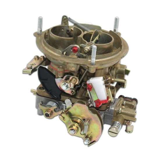
K-151S Carburetor
K-151D
The carburetor was installed on ZM34061.10 / ZM34063.10 engines, in which the ignition angle is controlled by an electronic brain.
The distributor was replaced with a DBP, which reads the parameters of the exhaust gas depression from the exhaust manifold, so the K-151D does not have a vacuum sampling device on the vacuum ignition timing controller.
For the same reason, there is no EPHX microswitch on the carb.
K-151V
The carburetor has a float chamber imbalance valve with a solenoid valve. On the back of the chamber there is a fitting to which the ventilation hose is connected. As soon as you turn off the ignition, the electromagnet opens access to the chamber, and excess gasoline vapors go into the atmosphere, thereby equalizing the pressure.
The need for such a system arose due to the installation of a carburetor on UAZ export models, which were supplied to countries with a hot climate.
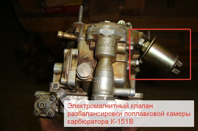
Solenoid valve for unbalancing the float chamber K-151V
The carburetor does not have the usual fuel outlet and vacuum supply to the EGR valve. The need for them will appear on later carburetor models with a standard fuel bypass system.
Summing up
The K-151 carburetor has established itself as a reliable, unpretentious and easy to operate. All breakdowns and shortcomings in it are easily eliminated. In the latest modifications, all the shortcomings of previous models have been eliminated. And if you set it up correctly and monitor the condition of the air filter, "151" will not bother you for a long time.
One comment
Alexander
there are a lot of errors instead of the minimum speed, it is written to set the maximum (almost stalls), instead of setting the speed on the tachometer, it is written to set the speed ... well, how can such mistakes be made ....