We study the scheme of electrical equipment VAZ 21074
Content
A driver who has a basic set of knowledge about the device and principles of operation of the VAZ 21074 electrical equipment will be able to diagnose and eliminate many malfunctions of the electrical part of his car on his own. Deal with breakdowns of electrical components and mechanisms of the VAZ 21074 will help special wiring diagrams and the location of devices in the car.
Wiring diagram VAZ 21074
In VAZ 21074 vehicles, electrical energy is delivered to consumers in a single-wire scheme: the "positive" output of each electrical appliance is powered from a source, the "negative" output is connected to the "mass", i.e. connected to the vehicle body. Thanks to this solution, the repair of electrical equipment is simplified and the corrosion process slows down. All electrical appliances of the car are powered by the battery (when the engine is off) or the generator (when the engine is running).
Also check out the electrical device VAZ 2107: https://bumper.guru/klassicheskie-modeli-vaz/elektrooborudovanie/elektroshema-vaz-2107.html
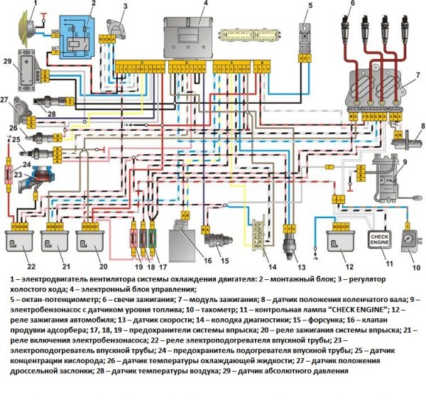
Wiring diagram VAZ 21074 injector
The injector versions of the "seven" released from the factory conveyor have indices:
- LADA 2107-20 - in accordance with the Euro-2 standard;
- LADA 2107-71 - for the Chinese market;
- LADA-21074–20 (Euro-2);
- LADA-21074–30 (Euro-3).
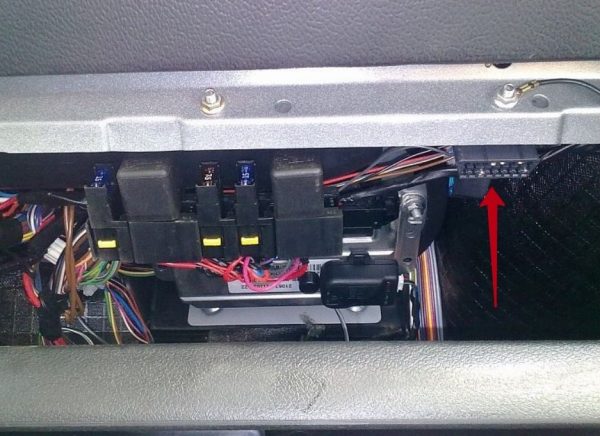
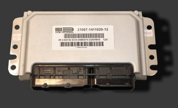
The injection modifications of the VAZ 2107 and VAZ 21074 use an ECM (electronic engine control system), an electric fuel pump, injectors, sensors for controlling and monitoring engine parameters. As a result, there was a need for additional engine compartment and interior wiring. In addition, the VAZ 2107 and VAZ 21074 are equipped with an additional relay and fuse box located under the glove box. Wiring is connected to the additional unit, powering:
- circuit breakers:
- power circuits of the main relay;
- circuits of a constant power supply of the controller;
- electric fuel pump relay circuits;
- relay:
- The main thing;
- fuel pump;
- electric fan;
- diagnostic connector.
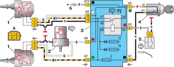
Wiring diagram VAZ 21074 carburetor
The electrical circuit of the carburetor "seven" largely coincides with the circuit of the injection version: the exception is the absence of engine control components. All electrical appliances VAZ 21074 are usually divided into systems:
- providing electricity;
- start;
- ignition;
- lighting and signaling;
- auxiliary equipment.
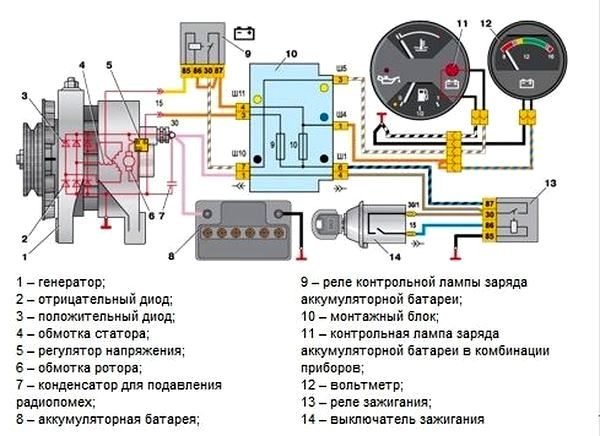
Electricity supply
The GXNUMX is responsible for providing consumers with electricity:
- Battery voltage 12 V, capacity 55 Ah;
- generator type G-222 or 37.3701;
- Ya112V voltage regulator, which automatically maintains the voltage within 13,6–14,7 V.
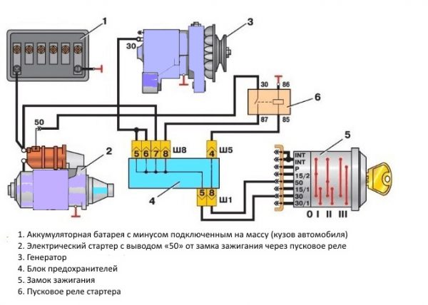
Engine starting
The starting system in the VAZ 21074 is a battery-powered starter and an ignition switch. There are two relays in the starter circuit:
- auxiliary, which supplies power to the starter terminals;
- retractor, due to which the starter shaft engages with the flywheel.
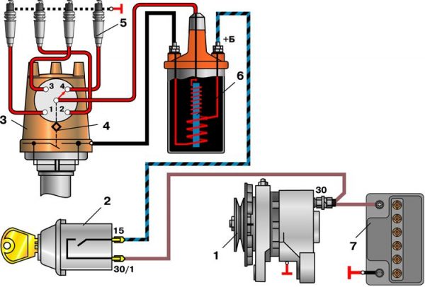
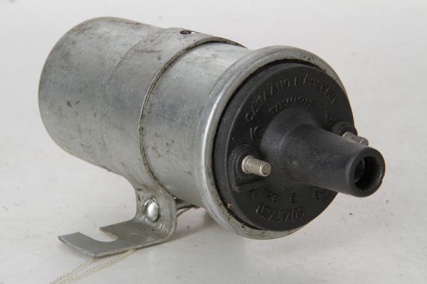
Ignition system
In early versions of the seventh VAZ model, a contact ignition system was used, which included:
- ignition coil;
- distributor with contact breaker;
- spark plug;
- high voltage wiring.
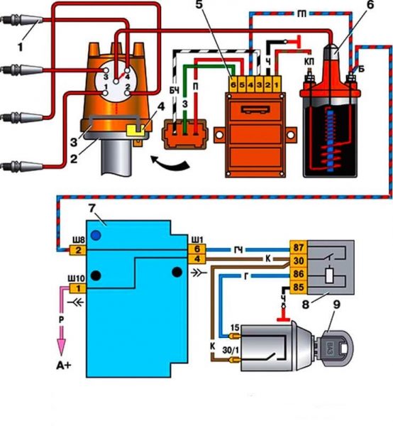
In 1989, the so-called contactless ignition system appeared, the scheme of which included:
- Spark plug.
- Distributor.
- Display.
- Hall Sensor.
- Electronic switch.
- Ignition coil.
- Mounting block.
- Relay block.
- Key and ignition switch.
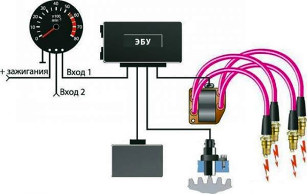
In the "sevens" with injection engines, a more modern ignition scheme is used. The operation of this circuit is based on the fact that the signals from the sensors are sent to the ECU (electronic control unit), which, based on the data received, generates electrical impulses and transmits them to a special module. After that, the voltage rises to the required value and is fed through high-voltage cables to the spark plugs.
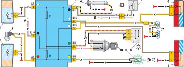
Outdoor Lighting
The outdoor lighting system includes:
- Block headlights with dimensions.
- Illumination of the engine compartment.
- Mounting block.
- Glove box lighting.
- Instrument illumination switch.
- Rear lights with dimensions.
- Room lighting.
- Outdoor light switch.
- Outdoor lighting indicator lamp (in the speedometer).
- Ignition.
Auxiliary equipment
Auxiliary or additional electrical equipment VAZ 21074 includes:
- electric motor:
- windshield washer;
- wiper;
- heater fan;
- cooling radiator fan;
- cigarette lighter;
- clock.
Wiper connection diagram uses:
- Gearmotors.
- ED washing machine.
- Mounting block.
- Egnition lock.
- Washer switch.
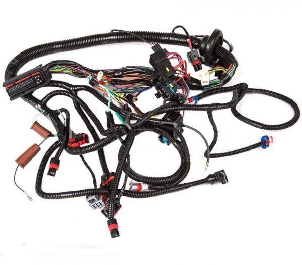
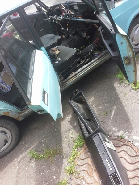
Underhood wiring
Three of the five wiring harnesses of the VAZ 21074 are located in the engine compartment. Inside the car, the harnesses are laid through technological holes equipped with rubber plugs.
Three bundles of wires located in the engine compartment can be seen:
- along the right mudguard;
- along the engine shield and the left mudguard;
- coming from the battery.
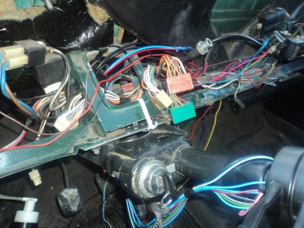
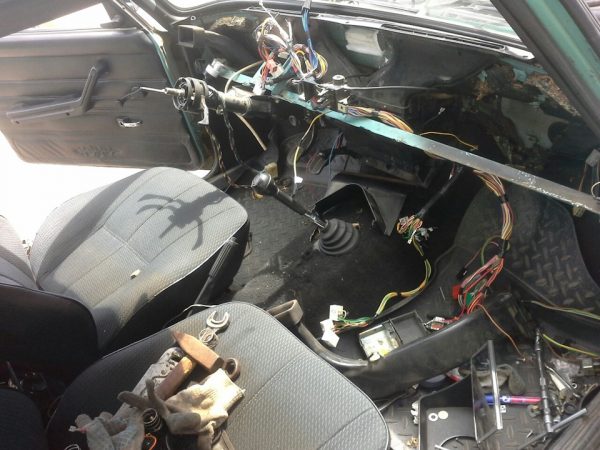
wiring harness in cabin
In the cabin of the VAZ 21074 there are wiring harnesses:
- under the instrument panel. This bundle contains wires responsible for headlights, direction indicators, dashboard, interior lighting;
- stretched from the fuse box to the rear of the car. The wires of this bundle are powered by the rear lights, glass heater, gasoline level sensor.
The wires that are used in the "seven" for electrical connections are of the PVA type and have a cross section of 0,75 to 16 mm2. The number of copper wires from which the wires are twisted can be from 19 to 84. The wiring insulation is made on the basis of polyvinyl chloride resistant to temperature overloads and chemical attack.
To simplify the repair, maintenance and replacement of electrical equipment, the factory wiring of VAZ 21074 vehicles has an established color scheme.
Table: section and color of the wiring of the most important electrical appliances VAZ 21074
| Electric circuit section | Wire section, mm2 | Insulation color |
| minus battery - "mass" of the body | 16 | the black |
| plus starter - battery | 16 | red |
| generator plus - battery | 6 | the black |
| alternator - black connector | 6 | the black |
| terminal "30" of the generator - white block MB | 4 | pink |
| starter terminal "50" - starter start relay | 4 | red |
| starter start relay - black connector | 4 | brown |
| ignition relay - black connector | 4 | blue |
| terminal "50" of the ignition lock - blue connector | 4 | red |
| terminal "30" of the ignition switch - green connector | 4 | pink |
| right headlight connector - "ground" | 2,5 | the black |
| left headlight connector - blue connector | 2,5 | green (grey) |
| terminal "15" of the generator - yellow connector | 2,5 | Orange |
| EM radiator fan - "ground" | 2,5 | the black |
| Radiator fan EM—red connector | 2,5 | blue |
| contact "30/1" of the ignition switch - ignition relay | 2,5 | brown |
| contact "15" of the ignition switch - single-pin connector | 2,5 | blue |
| cigarette lighter - blue connector | 1,5 | blue (red) |
How to replace wiring
If regular interruptions have begun in the operation of electrical equipment associated with faulty wiring, experts recommend replacing all wiring in the car. The same should be done after buying a car from the owner, who made changes to the scheme, added or improved something. Such changes affect the parameters of the on-board network, for example, the battery may discharge faster, etc. Therefore, it would be more correct for the new owner to bring everything back to its original form.
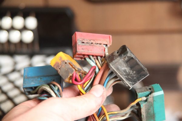
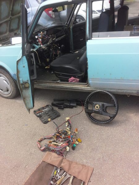
To replace the wiring in the cabin, you must:
- Remove the connectors from the mounting block.
 To start replacing the wiring, you need to remove the connectors from the mounting block
 - Remove the instrument panel and front trim.The next step is to remove the trim and instrument panel.
- Remove old wiring.Old wiring is unfastened and removed from the car
- Install new wiring in place of the old one.Install new wiring in place of old wiring.
- Restore the trim and replace the instrument panel.
If you need to replace the wiring of any electrical component of the VAZ 21074, but there are no "native" wires at hand, you can use similar products. For example, for the “seven”, a wiring with the following indices is suitable:
- 21053-3724030 - on the dashboard;
- 21053-3724035-42 - on the instrument panel;
- 21214-3724036 - for fuel injectors;
- 2101–3724060 — on starter;
- 21073-3724026 - to the ignition system;
- 21073-3724210-10 - flat back harness.
Simultaneously with the wiring, as a rule, the mounting block is also changed. It is better to install a new type of mounting block with plug-in fuses. It should be remembered that, despite the external similarity, mounting blocks can be of different types, so you need to look at the markings of the old block and install the same one. Otherwise, the electrical equipment may not work properly.
Video: specialist troubleshoots electricians VAZ 21074

We remove the panel and put it on the sly, there is nothing complicated there. First, we connect the panel and the interior, we stretch the braid under the hood to the place of the block. We scatter the wiring in the engine compartment: corrugation, clamps, so that nothing hangs or dangles. We put the block, connect it and you're done. I would also advise you to put normal terminals on the battery, regular garbage (at least on the standard ninth wiring). And buy two sets of Czech fuses, not impenetrable Chinese ones.
Electrical faults VAZ 21074 - how to identify and fix problems
If, after turning the ignition key, fuel enters the carburetor or VAZ 21074 injection frame, and the engine does not start, the cause should be sought in the electrical part. In a car with a carburetor engine, it is necessary to check, first of all, the breaker-distributor, the coil and spark plugs, as well as the wiring of this electrical equipment. If the car is equipped with an injection engine, the problem is most often in the ECM or burnt contacts in the ignition switch.
Carburetor engine
Having an idea about the operation of the electrical systems of the car, it is easier to determine the cause of the malfunction and eliminate it. For example, in a carbureted engine:
- ignition operation begins with the key being moved to the "Starter" position;
- after that, the generator is turned on;
- from the generator, an electrical signal is applied to a coil that generates a high voltage;
- through high-voltage wires, the voltage from the coil is supplied to the distributor;
- From the distributor, electrical impulses are sent to the electrodes of the spark plugs.
If the engine does not start after the ignition is turned on, this may be due to:
- break in the electrical circuit between the coil and the generator. It is necessary to verify the integrity of all contacts and wiring in this section of the circuit;
- coil winding failure. To check the health of the coil, you need to remove the power cable of the distributor, and with the engine running, touch it with the "ground" contacts. If a spark occurs at this point, the coil is good;
- interruption of the circuit between the distributor and spark plugs. It is necessary to ring the high-voltage cable in this area and check the integrity of the slider under the distributor cover.
If the car uses a contactless ignition system, an electronic switch installed between the coil and the distributor is additionally introduced into the circuit. The task of the switch is to receive signals from a proximity sensor and generate pulses applied to the primary winding of the coil: this helps to form a spark when running on lean fuel. The switch is checked in the same way as the coil: sparking on the supply wire of the distributor indicates that the switch is working.
More about the carburetor engine: https://bumper.guru/klassicheskie-modeli-vaz/dvigatel/dvigatel-vaz-2107.html
Injection engine
The injection engine is started due to:
- the use of an electric fuel pump, which is responsible for the formation of high pressure in the fuel system;
- the formation of a fuel mixture in the cylinders (and not in the carburetor);
- fuel injection by electric injectors;
- using the ECM, which determines the moment of fuel injection into the cylinder.
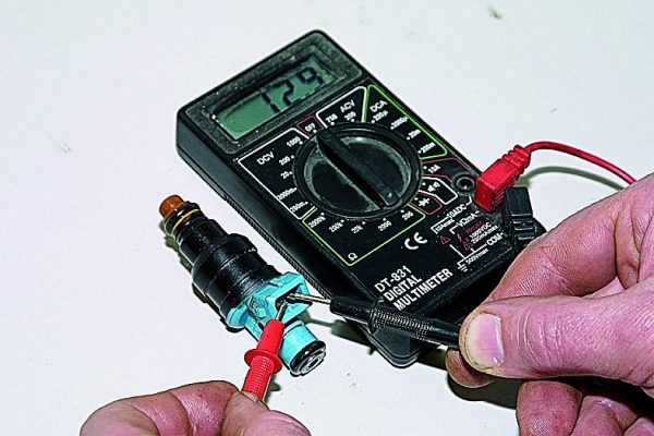
Interruptions in the ignition of an injection engine are most often associated with sensor malfunctions or a broken wiring. To check the integrity of the sensor, you must:
- Disconnect the connector and remove the sensor from the seat.
- Measure the resistance of the sensor.Remove the sensor and measure its resistance with a multimeter.
- Compare the result with the table, which can be found in the instructions for the electrical equipment of the car.
Diagnostics of malfunctions of auxiliary electrical equipment begins, as a rule, with the mounting block. If there are problems in the operation of lighting, sound and light alarms, a heater, a cooling fan or other devices, you must first check the integrity of the fuse that is responsible for this section of the circuit. Checking fuses, just like car electrical circuits, is done using a multimeter.
More about the VAZ 21074 model: https://bumper.guru/klassicheskie-modeli-vaz/poleznoe/vaz-21074-inzhektor.html
Table: typical malfunctions of electrical equipment VAZ 21074 and methods for their elimination
| Malfunction | Cause | How to fix |
| Battery drains quickly | Poor electrical contact. Loose fastening of the wire on the generator, mounting block, the battery terminals are not firmly fixed, etc. | Inspect all sections of the circuit: tighten all connections, clean oxidized contacts, etc. |
| Damaged insulation of electrical circuits, current leakage through the battery case | Measure the leakage current: if its value is greater than 0,01 A (with non-working consumers), you should look for damage to the insulation. Wipe the battery case with an alcohol solution | |
| When the engine is running, the battery discharge indicator lamp is on | Loose or broken alternator belt | Tighten the belt or replace it |
| Damage to the excitation circuit of the generator, failure of the voltage regulator | Clean the oxidized contacts, tighten the terminals, if necessary, replace the F10 fuse and the voltage regulator | |
| Starter does not crank | Damage to the control circuit of the starter retractor relay, i.e. when the ignition key is turned, the relay does not work (no characteristic click is heard under the hood) | Strip and tighten wire ends. Ring the contacts of the ignition switch and the retractor relay with a multimeter, if necessary, replace |
| The contacts of the retractor relay are oxidized, poor contact with the housing (a click is heard, but the starter armature does not rotate) | Clean contacts, crimp terminals. Ring the relay and starter windings, if necessary, replace | |
| The starter turns the crankshaft, but the engine does not start | Incorrectly set the gap between the contacts of the breaker | Adjust the gap within 0,35–0,45 mm. Take measurements with a feeler gauge |
| Hall sensor failed | Replace the hall sensor with a new one | |
| Individual filaments of the heater do not heat up | The switch, relay or heater fuse is out of order, the wiring is damaged, the contact connections of the circuit are oxidized | Ring all the elements of the circuit with a multimeter, replace the failed parts, clean the oxidized contacts, tighten the terminals |
Like any other vehicle system, the VAZ 21074 electrical equipment requires periodic inspection and maintenance. Given the venerable age of most of the "sevens" in use today, the electrical components of these machines, as a rule, require special attention. Timely maintenance of electrical equipment will ensure long-term trouble-free operation of the VAZ 21074.

