How to Port and Polish Your Car's Cylinder Heads
Content
Engine performance is increased when you port and polish cylinder heads in your vehicle. Save money by doing the work yourself instead of at the store.
One of the easiest ways to get 20 to 30 horsepower is to purchase ported and polished cylinder heads from the aftermarket. The engine will love the update, but your wallet might not. Today's aftermarket cylinder heads are highly priced.
To ease the financial burden a bit, you can send the cylinder head to a machine shop for porting and polishing, but it will be expensive. The best way to save as much money as possible and get the same performance benefits is to spend your own time porting and polishing the cylinder head yourself.
The porting and polishing process is generally the same for all cylinder heads. Below we will provide a simple guide to properly, safely and effectively porting and polishing cylinder heads. However, keep in mind that everything suggested in this article is done at your own risk. It is very easy to grind off too much metal, which is irreversible and most likely will result in an unusable cylinder head.
- Attention: If you have little to no experience with Dremel, it is recommended to practice on a replacement cylinder head first. Old replacement cylinder heads can be bought at a junkyard, or a store can give you an old head for free.
Part 1 of 6: Getting Started
Necessary materials
- 2-3 cans of brake cleaner
- Scotch-Brite pads
Work gloves
FunctionsA: This whole process will take some time. Possibly 15 business hours or more. Please be patient and resolute during this procedure.
Step 1: Remove the cylinder head.. This process will vary from engine to engine so you should refer to the manual for details.
Typically, you will need to remove any obstructing parts from the head, and you will need to remove the nuts and bolts holding the head.
Step 2: Remove the camshaft, rocker arms, valve springs, retainers, valves and tappets.. You should refer to your manual for details on removing them as every car is very different.
- Functions: Each removed component must be reinstalled in exactly the same location from which it was removed. When disassembling, arrange the removed components so that the original position can be easily traced.
Step 3: Thoroughly clean the cylinder head of oil and debris with a brake cleaner.. Scrub with a gold wire brush or Scotch-Brite pad to remove stubborn deposits.
Step 4: Inspect the cylinder head for cracks. Most often they appear between adjacent valve seats.
- Functions: If a crack is found in the cylinder head, the cylinder head must be replaced.
Step 5: Clean up the junction. Use a Scotch-Brite sponge or 80 grit sandpaper to clean the area where the cylinder head meets the intake manifold gasket to bare metal.
Part 2 of 6: Increase airflow
- Dykem Machinist
- Wire brush with golden bristles
- High speed Dremel (over 10,000 rpm)
- Lapping tool
- Lapping compound
- Penetrating oil
- Porting and polishing kit
- Safety glasses
- Small screwdriver or other pointed metal object.
- Surgical masks or other respiratory protection
- Work gloves
- Ties
Step 1: Fit the intake ports to the intake gaskets.. By pressing the intake manifold gasket against the cylinder head, you can see how much metal can be removed to increase airflow.
The inlet can be widened considerably to match the circumference of the inlet gasket.
Step 2: Paint the perimeter of the inlet with Machinist Red or Blue.. After the paint has dried, connect the intake manifold gasket to the cylinder head.
Use an intake manifold bolt or tape to hold the gasket in place.
Step 3: Circle the inlet. Use a small screwdriver or similar sharp object to mark or trace areas around the inlet where paint is visible.
Step 4: Remove the material inside the labels. Use a rock tool with an arrow to moderately remove the material inside the marks.
A headstone with an arrow will leave a rough surface, so be extremely careful not to over-enlarge the port or mistakenly sand the area that comes into the intake gasket coverage area.
Enlarge the intake manifold evenly and evenly. No need to go too deep inside the runner. You just need to insert from an inch to an inch and a half into the inlet pipe.
Keep your Dremel speed around 10,000-10,000 rpm otherwise the bits will wear out faster. Take into account the Dremel factory RPM you are using to determine how much faster or slower the RPM needs to be adjusted to reach the XNUMX RPM range.
For example, if the Dremel you're using has a factory RPM of 11,000-20,000 RPM, it's safe to say that you can run it to its full potential without burning the bits. On the other hand, if the Dremel has a factory RPM of XNUMXXNUMX, then hold the throttle at about halfway to the point where the Dremel is running at about half speed.
- A warning: Do not remove metal protruding into the gasket coverage area, otherwise leakage may occur.
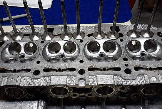
Functions: Sand out any sharp bends, crevices, crevices, casting irregularities and casting protrusions inside the intake port where possible. The following image shows an example of casting irregularities and sharp edges.
Functions: Be sure to enlarge the port evenly and evenly. Once the first slider is enlarged, use a cut wire hanger to evaluate the enlargement process. Cut the hanger to a length that matches the width of the first ported outlet. So you can use the cut out hanger as a template to get a better idea of how much the other skids need to be enlarged. Each inlet extension should be approximately equal to each other so that they can pass the same volume. The same rule applies to exhaust guides.
Step 4: Smooth out the new surface area. Once the inlet is enlarged, use less coarse cartridge rollers to smooth out the new surface area.
Use a 40 grit cartridge to do most of the sanding and then use an 80 grit cartridge to get a nice smooth finish.
Step 5: Inspect the inlets. Turn the cylinder head upside down and inspect the inside of the intake rails through the valve holes.
Step 6: Remove Any Obvious Bumps. Sand down any sharp corners, crevices, crevices, rough castings and casting irregularities with cartridges.
Use a 40 grit cartridge to evenly space the inlet channels. Focus on correcting any shortcomings. Then use an 80 grit cartridge to smooth out the hole area even more.
- Functions: When grinding, be extremely careful not to grind any areas where the valve officially makes contact with the cylinder head, also known as the valve seat, otherwise new valve performance will result.
Step 7: Finish Other Inlets. After finishing the first inlet, move on to the second inlet, the third, and so on.
Part 3 of 6: Porting the exhaust pipe
Without porting the exhaust side, the engine will not have enough displacement to efficiently exit the increased air volume. For transferring the exhaust side of the engine, the steps are very similar.
- Dykem Machinist
- Wire brush with golden bristles
- High speed Dremel (over 10,000 rpm)
- Penetrating oil
- Porting and polishing kit
- Safety glasses
- Small screwdriver or other pointed metal object.
- Surgical masks or other respiratory protection
- Work gloves
Step 1: Clean up the docking area. Use a Scotch-Brite cloth to clean the area where the cylinder head meets the exhaust gasket to bare metal.
Step 2: Paint the perimeter of the exhaust with Machinist Red or Blue.. After the paint has dried, connect the exhaust manifold gasket to the cylinder head.
Use an exhaust manifold bolt or tape to hold the gasket in place.
Step 3: Mark the areas where the paint is showing with a very small screwdriver or similar sharp object.. Use the images in step 9 as references if necessary.
Sand down any roughness in the casting or unevenness in the casting because carbon deposits can easily accumulate in unattended areas and cause turbulence.
Step 4: Enlarge the port opening to match the marks.. Use the Arrowhead stone attachment to do the most of the sanding.
- Attention: The stone arrow head will leave a rough surface, so it may not look the way you expect for now.
- Functions: Be sure to enlarge the port evenly and evenly. Once the first branch is enlarged, use the cut wire suspension technique mentioned above to evaluate the enlargement process.
Step 5. Transfer the outlet extension with cartridges.. This will give you a nice smooth surface.
Start with a 40 grit cartridge to get most of the conditioning done. After a thorough surface treatment with a 40 grit cartridge, use an 80 grit cartridge to obtain a smooth surface without ripples.
Step 6: Continue with the remaining exhaust rails.. After the first outlet is properly connected, repeat these steps for the rest of the outlets.
Step 7: Inspect the exhaust guides.. Place the cylinder head upside down and inspect the inside of the exhaust guides through the valve holes for defects.
Step 8: Remove any roughness or imperfections. Sand all sharp corners, crevices, crevices, rough castings and casting irregularities.
Use a 40 grit cartridge to evenly space the exhaust passages. Focus on removing any imperfections, then use an 80 grit cartridge to further smooth out the hole area.
A warning: As previously stated, be very careful not to mistakenly grind any of the areas where the valve officially makes contact with the cylinder head, also known as the valve seat, or severe permanent damage may occur.
Functions: After using a steel carbide tip, switch to a less coarse chuck roller to further smooth the surface where needed.
Step 9: Repeat for the rest of the exhaust guides.. Once the end of the first exhaust rail is correctly installed, repeat the procedure for the rest of the exhaust rails.
Part 4 of 6: Polishing
- Dykem Machinist
- Wire brush with golden bristles
- High speed Dremel (over 10,000 rpm)
- Penetrating oil
- Porting and polishing kit
- Safety glasses
- Small screwdriver or other pointed metal object.
- Surgical masks or other respiratory protection
- Work gloves
Step 1: Polish the inside of the slider. Use the flap from the porting and polishing kit to polish the inside of the slider.
You should see a magnification and sparkle as you move the shutter over the surface. It is only necessary to polish the inside of the inlet pipe about an inch and a half. Polish the inlet evenly before moving on to the next buffer.
- Functions: Remember to keep your Dremel spinning at around 10000 RPM to maximize bit life.
Step 2: Use a medium grit grinding wheel.. Repeat the same process as above, but use a medium grain cross buffer instead of a flapper.
Step 3: Use a Fine Cross Buffer. Repeat the same process one more time, but use a fine grit sanding wheel for the final finish.
It is recommended to spray the buffer and guide with a small amount of WD-40 to add shine and shimmer.
Step 4: Complete for the Remaining Runners. After the first inlet has been successfully polished, move on to the second inlet, the third, and so on.
Step 5: Polish the Exhaust Guides. When all inlet guides are polished, proceed to polishing the exhaust guides.
Polish each exhaust pipe using exactly the same instructions and buffer sequence as described above.
Step 6: Polish Out Runners. Place the cylinder head upside down so we can polish the intake and exhaust ports.
Step 7: Apply the same buffer sequence. To polish both the inlet and outlet ports, use the same buffer sequence as previously used.
Use a flap for the first polishing step, then a medium grit cross wheel for the second step, and a fine grit cross wheel for the final polish. In some cases, the damper may not fit into bottlenecks. If this is the case, use a medium grit cross buffer to cover areas that the shutter cannot reach.
- Functions: Remember to spray WD-40 in small batches using a fine cross buffer to enhance shine.
Step 8: Focus on the bottom of the cylinder head.. Now let's focus on porting and polishing the bottom of the cylinder head.
The goal here is to eliminate the rough surface that can cause pre-ignition and clean up carbon deposits. Place the valves in their original locations to protect the valve seats during porting.
Part 4 of 6: polishing the cylinder deck and chamber
- Dykem Machinist
- High speed Dremel (over 10,000 rpm)
- Penetrating oil
- Porting and polishing kit
- Safety glasses
- Small screwdriver or other pointed metal object.
- Surgical masks or other respiratory protection
- Work gloves
- Ties
Step 1: Use the cartridge rollers to smooth the area where the chamber meets the deck.. Tie zip ties around the valve stem to secure the valves in place.
An 80 grit cartridge should be sufficient for this porting step. Perform this step on each platform and cylinder chamber.
Step 2: Polish the cylinder head. After each cylinder head has been ported, we will polish them using almost the same methods as before.
This time polish using only a fine cross buffer. At this point you should really start to see the flickering of the cylinder head. For a cylinder head to really shine bright like a diamond, use a fine cross buffer to achieve the final shine.
Functions: Remember to keep your Dremel spinning at around 10000 RPM to maximize bit life.
Functions: Remember to spray WD-40 in small batches using a fine cross buffer to enhance shine.
Part 6 of 6: Complete valve seating
- Dykem Machinist
- Lapping tool
- Lapping compound
- Surgical masks or other respiratory protection
- Work gloves
We will then safely repair your valve seats. This reconditioning process is known as valve lapping.
Step 1: Paint the perimeter of the valve seats blue red or blue.. The paint will help visualize the lapping pattern and indicate when lapping is complete.
Step 2: Apply the compound. Apply lapping compound to the valve base.
Step 3: Apply the Lapping Tool. Return the valve to its original position and apply a lapping tool.
With little effort, rotate the lapping tool between your hands at a fast pace, as if you were warming your hands or trying to start a fire.
Step 4: Inspect the Template. After a few seconds, remove the valve from the seat and inspect the resulting pattern.
If a shiny ring forms on the valve and seat, your job is done and you can move on to the next valve and valve seat. If not, there's a good chance you have a bent valve that needs to be replaced.
Step 5: Reinstall any components you removed. Reinstall the camshaft, rocker arms, valve springs, retainers and tappets.
Step 6: Reinstall the cylinder head.. When finished, double check the time before starting the car.
All the time spent polishing, polishing, sanding and lapping paid off. To check the results of the work, take the cylinder head to the machine shop and test it on the bench. The test will identify any leaks and allow you to see the amount of airflow going through the skids. You want the volume through each inlet to be very similar. If you have any questions about the process, see your mechanic for quick and helpful advice and be sure to replace the cylinder head temperature sensor if necessary.