How the fuel injection system of the VAZ 2107 is arranged and works
Content
- Fuel system VAZ 2107 injector
- The main malfunctions of the injection fuel system and their symptoms
- How to find a fault
- How to check and flush the injector
- How to convert a VAZ 2107 carburetor engine to an injection engine
The use of a fuel system with distributed injection on the VAZ 2107 allowed this last representative of the "classic" to successfully compete with front-wheel drive models of domestic production and hold out on the market until 2012. What is the secret of the popularity of the injection "seven"? This is what we will try to figure out.
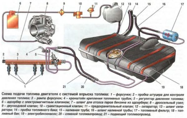
Fuel system VAZ 2107 injector
With the introduction in 2006 on the territory of the Russian Federation of mandatory European environmental standards EURO-2, the Volga Automobile Plant was forced to convert the fuel system of the "seven" from a carburetor to an injector. The new car model became known as the VAZ 21074. At the same time, neither the body nor the engine underwent any changes. It was still the same popular "seven", only much faster and more economical. It was thanks to these qualities that she received a new life.
Tasks of the power system
The fuel system of the power unit of the car is used to supply fuel from the tank to the line, clean it, prepare a high-quality mixture of air and gasoline, as well as its timely injection into the cylinders. The slightest failures in its operation lead to the loss of the motor of its power qualities or even disable it.
The difference between a carburetor fuel system and an injection system
In the carburetor VAZ 2107, the power plant power system included exclusively mechanical components. The diaphragm-type fuel pump was driven by a camshaft, and the driver himself controlled the carburetor by adjusting the position of the air damper. In addition, he himself had to exhibit, and the quality of the combustible mixture supplied to the cylinders, and its quantity. The list of mandatory procedures also included setting the ignition timing, which the owners of carburetor cars had to do almost every time the quality of the fuel poured into the tank changed. In injection machines, none of this is necessary. All these processes are controlled by the "brain" of the car - the electronic control unit (ECU).
But this is not the main thing. In carburetor engines, gasoline is supplied to the intake manifold in a single stream. There, it somehow mixes with air and is sucked into the cylinders through the valve holes. In injection power units, thanks to the nozzles, the fuel does not enter in liquid form, but practically in gaseous form, which allows it to mix better and faster with air. Moreover, fuel is supplied not just to the manifold, but to its channels connected to the cylinders. It turns out that each cylinder has its own nozzle. Therefore, such a power supply system is called a distributed injection system.
Advantages and disadvantages of the injector
The power supply system of the power plant with distributed injection has its advantages and disadvantages. The latter include the complexity of self-diagnosis and high prices for individual elements of the system. As for the advantages, there are much more of them:
- no need to adjust the carburetor and ignition timing;
- simplified start of a cold engine;
- a noticeable improvement in the power characteristics of the engine during start-up, acceleration;
- significant fuel savings;
- the presence of a system for informing the driver in case of errors in the operation of the system.
The design of the power supply system VAZ 21074
The fuel system of the "seven" with distributed injection includes the following elements:
- gas tank;
- fuel pump with primary filter and fuel level sensor;
- fuel line (hoses, tubes);
- secondary filter;
- ramp with pressure regulator;
- four nozzles;
- air filter with air ducts;
- throttle module;
- adsorber;
- sensors (idle, air flow, throttle position, oxygen concentration).
 The operation of the system system is controlled by the ECU
Consider what they are and what they are intended for.
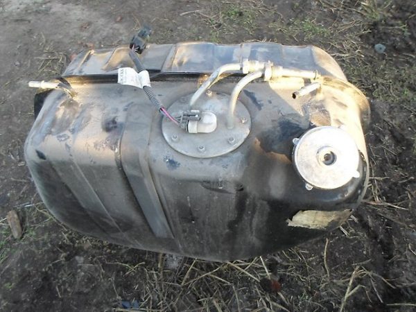
Fuel tank
The container is used to store gasoline. It has a welded construction consisting of two halves. The tank is located in the lower right part of the luggage compartment of the car. Its neck is brought out into a special niche, which is located on the right rear fender. The capacity of the VAZ 2107 tank is 39 liters.
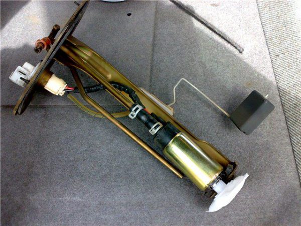
Fuel pump and fuel gauge
The pump is needed to select and supply fuel from the tank to the fuel line, to create a certain pressure in the system. Structurally, this is a conventional electric motor with blades on the front of the shaft. It is they who pump gasoline into the system. A coarse fuel filter (mesh) is located on the inlet pipe of the pump housing. It retains large particles of dirt, preventing them from entering the fuel line. The fuel pump is combined into one design with a fuel level sensor that allows the driver to see the amount of remaining gasoline. This node is located inside the tank.
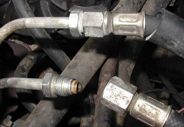
Fuel line
The line ensures the unhindered movement of gasoline from the tank to the injectors. Its main part is metal tubes interconnected by fittings and flexible rubber hoses. The line is located under the bottom of the car and in the engine compartment.
Secondary filter
The filter is used to clean gasoline from the smallest particles of dirt, corrosion products, water. The basis of its design is a paper filter element in the form of corrugations. The filter is located in the engine compartment of the machine. It is mounted on a special bracket to the partition between the passenger compartment and the engine compartment. The body of the device is non-separable.
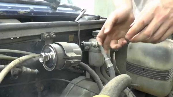
Rail and pressure regulator
The fuel rail of the "seven" is a hollow aluminum bar, thanks to which gasoline from the fuel line enters the nozzles installed on it. The ramp is attached to the intake manifold with two screws. In addition to the injectors, it has a fuel pressure regulator that maintains the operating pressure in the system in the range of 2,8–3,2 bar.
Nozzles
So we come to the main parts of the injector power system - injectors. The word "injector" itself comes from the French word "injecteur", denoting the injection mechanism. In our case, it is a nozzle, of which there are only four: one for each cylinder.
Injectors are the executive elements of the fuel system that supply fuel to the engine intake manifold. Fuel is injected not into the combustion chambers themselves, as in diesel engines, but into the collector channels, where it mixes with air in the right proportion.
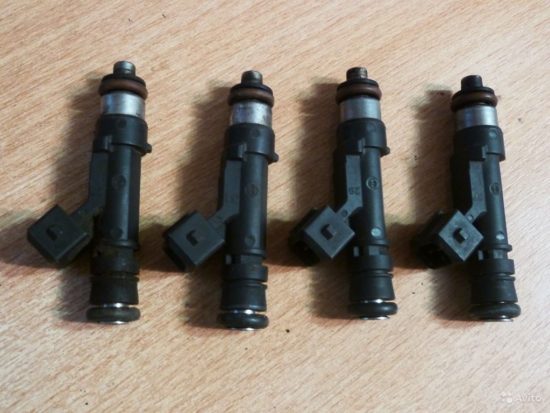
The basis of the nozzle design is a solenoid valve that is triggered when an electric current pulse is applied to its contacts. It is at the moment the valve opens that fuel is injected into the manifold channels. The duration of the pulse is controlled by the ECU. The longer the current is supplied to the injector, the more fuel is injected into the manifold.
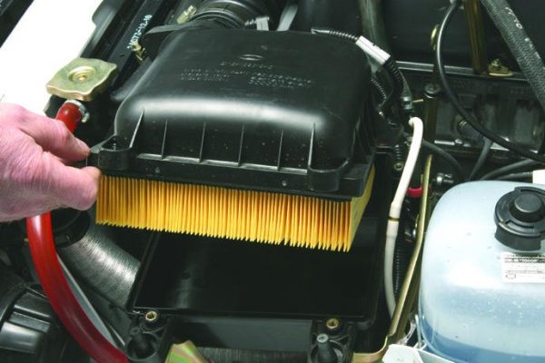
Air filter
The role of this filter is to clean the air entering the collector from dust, dirt and moisture. The body of the device is located to the right of the engine in the engine compartment. It has a collapsible design, inside which there is a replaceable filter element made of special porous paper. Rubber hoses (sleeves) fit the filter housing. One of them is an air intake through which air enters the filter element. The other sleeve is designed to supply air to the throttle assembly.
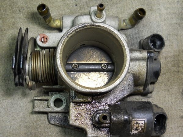
Throttle assembly
The throttle assembly includes a damper, its drive mechanism and fittings for supplying (removing) the coolant. It is designed to regulate the volume of air supplied to the intake manifold. The damper itself is driven by a cable mechanism from the accelerator pedal of the car. The damper body has a special channel through which coolant circulates, which is supplied to the fittings through rubber hoses. This is necessary so that the drive mechanism and damper do not freeze in the cold season.
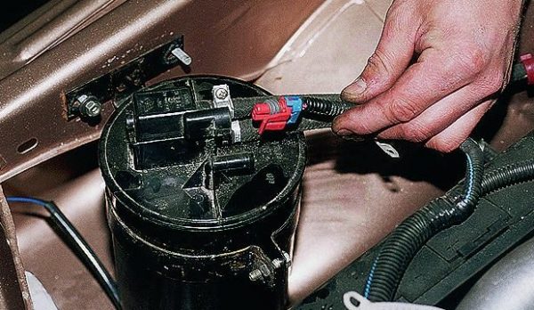
Adsorber
The adsorber is an optional element of the power system. The engine can work fine without it, however, in order for a car to meet EURO-2 requirements, it must be equipped with a fuel vapor recovery mechanism. It includes an adsorber, a purge valve, and safety and bypass valves.
The adsorber itself is a sealed plastic container filled with crushed activated carbon. It has three fittings for pipes. Through one of them, gasoline vapors enter the tank, and are held there with the help of coal. By means of the second fitting, the device is connected to the atmosphere. This is necessary to equalize the pressure inside the adsorber. The third fitting is connected by a hose to the throttle assembly through the purge valve. At the command of the electronic control unit, the valve opens, and gasoline vapor enters the damper housing, and from it into the manifold. Thus, the vapors accumulated in the tank of the machine are not emitted into the atmosphere, but are consumed as fuel.
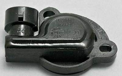
SENSORS
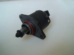
Sensors are used to collect information about the operating modes of the engine and transfer it to the computer. Each of them has its own purpose. The idle speed sensor (regulator) controls and regulates the flow of air into the manifold through a special channel, opening and closing its hole by the value set by the ECU when the power unit is operating without load. The regulator is built into the throttle module.
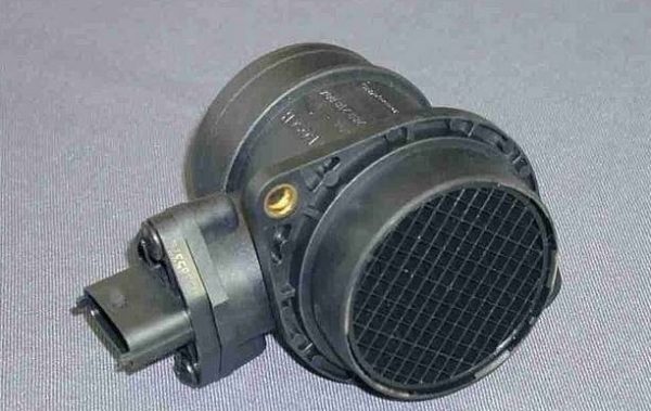
The mass air flow sensor is used to collect information about the volume of air passing through the air filter. By analyzing the data received from it, the ECU calculates the amount of gasoline required to form the fuel mixture in optimal proportions. The device is installed in the air filter housing.
Thanks to the throttle position sensor mounted on the body of the device, the ECU “sees” how much it is ajar. The data obtained is also used to accurately calculate the composition of the fuel mixture. The design of the device is based on a variable resistor, the movable contact of which is connected to the damper axis.
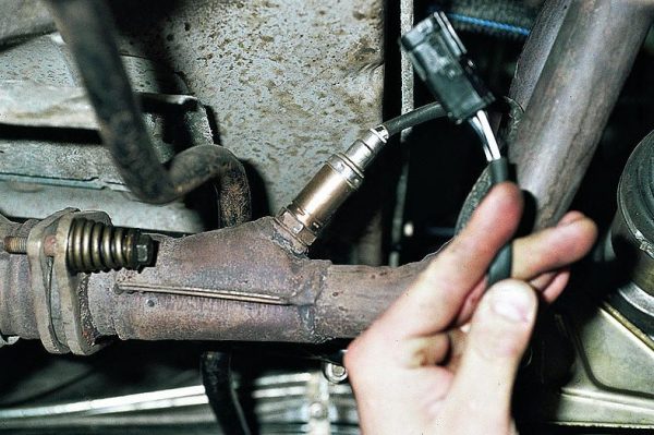
An oxygen sensor (lambda probe) is needed so that the “brain” of the car receives information about the amount of oxygen in the exhaust gases. These data, as in previous cases, are needed to form a high-quality combustible mixture. The lambda probe in the VAZ 2107 is installed on the exhaust pipe of the exhaust manifold.
The main malfunctions of the injection fuel system and their symptoms
Before moving on to malfunctions of the GXNUMX fuel system, let's consider what symptoms may accompany them. Signs of a system malfunction include:
- difficult start of a cold power unit;
- unstable engine idling;
- "floating" engine speed;
- loss of power qualities of the motor;
- increased fuel consumption.
Naturally, similar symptoms can occur with other engine malfunctions, especially those related to the ignition system. In addition, each of them can indicate several types of breakdowns at the same time. Therefore, when diagnosing, an integrated approach is important here.
Difficult cold start
Problems with starting a cold unit can occur when:
- fuel pump malfunctions;
- reducing the throughput of the secondary filter;
- nozzle clogging;
- failure of the lambda probe.
Unstable motor operation without load
Violations in the engine idling may indicate:
- malfunctions of the XX regulator;
- breakdown of the fuel pump;
- nozzle clogging.
"Floating" turns
Slow movement of the tachometer needle, first in one direction, then in the other direction may be a sign of:
- idle speed sensor malfunctions;
- failure of the air flow sensor or throttle position;
- malfunctions in the fuel pressure regulator.
Loss of power
The power unit of the injection "seven" becomes significantly weaker, especially under load, with:
- violations in the operation of the injectors (when fuel is not injected into the manifold, but flows, as a result of which the mixture becomes too rich, and the engine “chokes” when the gas pedal is pressed sharply);
- failure of the throttle position sensor;
- interruptions in the operation of the fuel pump.
All of the above malfunctions are accompanied by an increase in fuel consumption.
How to find a fault
You need to look for the cause of a fuel system malfunction in two directions: electrical and mechanical. The first option is the diagnostics of sensors and their electrical circuits. The second is a pressure test in the system, which will show how the fuel pump works and how gasoline is delivered to the injectors.
Error Codes
It is recommended to start searching for any breakdown in an injection car by reading the error code issued by the electronic control unit, because most of the listed power system malfunctions will be accompanied by the “CHECK” light on the dashboard. To do this, you can contact a service station, or carry out diagnostics yourself if you have a scanner designed for this. The table below shows the error codes in the operation of the VAZ 2107 fuel system with decoding.
Table: error codes and their meaning
| Code | transcript |
| Р 0102 | Malfunction of the mass air flow sensor or its circuit |
| Р 0122 | Throttle Position Sensor or Circuit Malfunction |
| P 0130, P 0131, P 0132 | Lambda probe malfunction |
| P 0171 | The mixture entering the cylinders is too lean |
| P 0172 | The mixture is too rich |
| Р 0201 | Violations in the operation of the nozzle of the first cylinder |
| Р 0202 | Violations in the operation of the nozzle of the second cylinder |
| Р 0203 | Violations in the operation of the nozzle of the third cylinder |
| Р 0204 | Violations in the operation of the fourth injector cylinder |
| Р 0230 | The fuel pump is faulty or there is an open circuit in its circuit |
| Р 0363 | The fuel supply to the cylinders where the misfires are recorded is turned off |
| P 0441, P 0444, P 0445 | Problems in the operation of the adsorber, purge valve |
| Р 0506 | Violations in the work of the idle speed controller (low speed) |
| Р 0507 | Violations in the work of the idle speed controller (high speed) |
| P 1123 | Too rich mixture at idle |
| P 1124 | Too lean mixture at idle |
| P 1127 | Too rich mixture under load |
| P 1128 | Too lean under load |
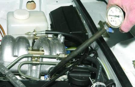
Checking the rail pressure
As mentioned above, the operating pressure in the power supply system of the injector “seven” should be 2,8–3,2 bar. You can check whether it corresponds to these values using a special liquid manometer. The device is connected to the fitting located on the fuel rail. Measurements are taken with the ignition on without starting the engine and with the power unit running. If the pressure is less than normal, the problem should be sought in the fuel pump or fuel filter. It is also worth inspecting the fuel lines. They may be damaged or pinched.
How to check and flush the injector
Separately, we should talk about nozzles, because it is they who most often fail. The cause of disturbances in their work is usually either an open in the power circuit or a clog. And if in the first case the electronic control unit will necessarily signal this by turning on the “CHECK” lamp, then in the second case the driver will have to figure it out himself.
Clogged injectors usually either do not pass fuel at all, or simply pour it into the manifold. To assess the quality of each of the injectors at service stations, special stands are used. But if you do not have the opportunity to carry out diagnostics at the service station, you can do it yourself.
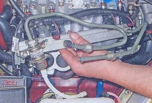
Removing the receiver and fuel rail
To access the injectors, we need to remove the receiver and ramp. For this you need:
- Disconnect the power supply of the on-board network by disconnecting the negative terminal from the battery.
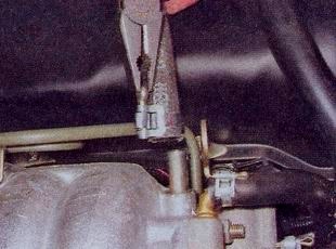
- Using pliers, loosen the clamp and remove the vacuum booster hose from the fitting.Clamps are loosened with pliers
- Using the same tool, loosen the clamps and disconnect the coolant inlet and outlet hoses, crankcase ventilation, fuel vapor supply, and the air duct sleeve from the fittings on the throttle body.
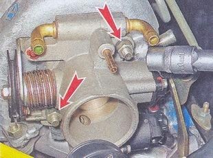
- Using a 13 wrench, unscrew the two nuts on the studs securing the throttle assembly.The throttle assembly is mounted on two studs and fastened with nuts
- Remove the throttle body together with the gasket.A sealing gasket is installed between the damper body and the receiver
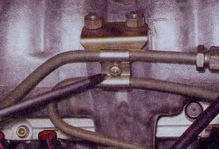
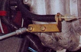
- Using a Phillips screwdriver, remove the fuel pipe bracket screw. Remove bracket.Remove one screw to remove the bracket.
- With a 10 wrench (preferably a socket wrench), unscrew the two bolts of the throttle cable holder. Move the holder away from the receiver.To remove the holder, unscrew the two screws.
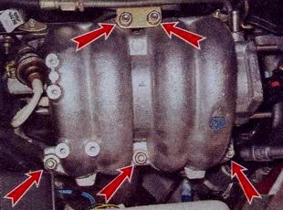
- Using a 13 socket wrench, unscrew the five nuts on the studs securing the receiver to the intake manifold.The receiver is attached with five nuts
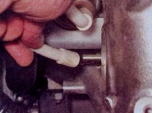
- Disconnect the pressure regulator hose from the receiver fitting.Hose can be easily removed by hand
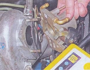
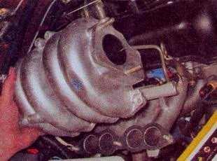
- Remove the receiver along with the gasket and spacers.Gasket and spacers are located under the receiver
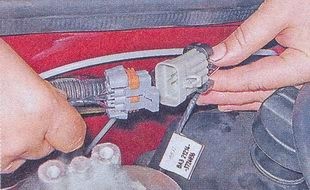
- Disconnect the engine harness connectors.The wires in this harness supply power to the injectors.
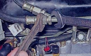
- Using two 17 open-end wrenches, unscrew the fitting of the fuel drain pipe from the rail. This may cause a small amount of fuel to splash out. Gasoline spills must be wiped off with a dry cloth.
- Disconnect the fuel supply pipe from the rail in the same way.The tube fittings are unscrewed with a key of 17
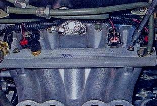
- Using a 5mm hex wrench, unscrew the two screws securing the fuel rail to the manifold.The ramp is attached to the manifold with two screws.
- Pull the rail towards you and remove it complete with injectors, pressure regulator, fuel pipes and wiring.
Video: removing the ramp VAZ 21074 and replacing nozzles

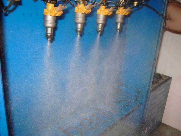
Checking injectors for performance
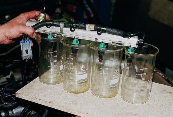
Now that the ramp is removed from the engine, you can begin to diagnose. This will require four containers of the same volume (plastic glasses or better 0,5 liter bottles), as well as an assistant. The check procedure is as follows:
- We connect the connector of the ramp to the connector of the motor harness.
- Attach the fuel lines to it.
- We fix the ramp horizontally in the engine compartment so that plastic containers can be installed under the nozzles.The ramp must be installed horizontally and a container for collecting gasoline should be placed under each of the nozzles
- Now we ask the assistant to sit down on the steering wheel and turn the starter, simulating the start of the engine.
- While the starter is turning the engine, we observe how fuel enters the tanks from the injectors: it is sprayed to the beat, or it pours.
- We repeat the procedure 3-4 times, after which we check the volume of gasoline in the containers.
- Having identified the faulty nozzles, we remove them from the ramp and prepare for flushing.
Flushing nozzles
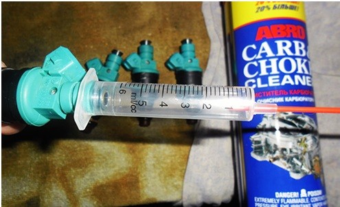
Injector clogging occurs due to the presence of dirt, moisture, and various impurities in gasoline, which settle on the working surfaces of the nozzles and eventually narrow them or even block them. The task of flushing is to dissolve these deposits and remove them. To complete this task at home, you will need:
- liquid for cleaning carburetors;
- five-cube medical syringe;
- plastic bottle;
- two pieces of wire with terminals and clamps;
- insulating tape;
- stationery knife.
The order of work is as follows:
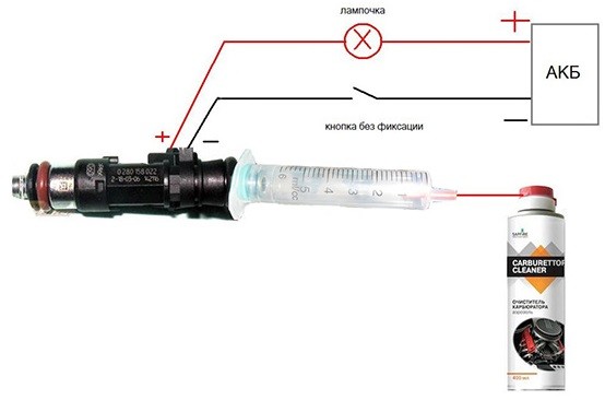
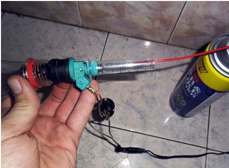
- We connect the wires to the terminals of the nozzle, isolate the connections.It is better to clean the nozzles with a special liquid
- Remove the plunger from the syringe.
- With a clerical knife, we cut off the “nose” of the syringe so that it can be tightly inserted into the tube that comes with the carburetor flushing fluid. We insert the tube into the syringe and connect it to the cylinder with liquid.The “nose” of the syringe must be cut so that the tube of the liquid cylinder fits tightly into it
- We put the syringe on the side where the piston was on the inlet end of the nozzle.
- Place the other end of the nozzle in a plastic bottle.
- We connect the positive wire of the injector to the corresponding terminal of the battery.
- We press the cylinder button, releasing the flushing liquid into the syringe. Connect the negative wire to the battery at the same time. At this time, the nozzle valve will open and flushing liquid will begin to flow through the channel under pressure. We repeat the procedure several times for each of the injectors.Purge must be repeated several times for each of the nozzles
Of course, this method can not always help return the injectors to their previous performance. If the nozzles continue to "snot" after cleaning, it is better to replace them. The cost of one injector, depending on the manufacturer, varies from 750 to 1500 rubles.
Video: flushing VAZ 2107 nozzles

How to convert a VAZ 2107 carburetor engine to an injection engine
Some owners of the carburetor "classics" independently convert their cars to the injector. Naturally, such work requires a certain experience in car mechanic business, and knowledge in the field of electrical engineering is indispensable here.
What will you need to buy
A kit for converting a carburetor fuel system to an injection system includes:
- electronic control unit;
- gas tank;
- cylinder head (new or used from VAZ 21214);
- receiver;
- ramp with nozzles;
- fuel pump assembly;
- fuel filter;
- fuel line with rubber hoses;
- throttle assembly;
- accelerator pedal with cable;
- air filter assembly with sleeves;
- engine front cover;
- crankshaft pulley;
- ignition module;
- sensors for mass air flow, damper position, detonation, coolant temperature, oxygen concentration, crankshaft position, detonation;
- high voltage wires;
- bundles, cables, wires, terminals, thermo-cambric;
- brackets.
The cost of all these elements is about 30 thousand rubles. The electronic control unit alone costs about 5-7 thousand. But costs can be significantly reduced if you buy not new parts, but used ones.
Stages of conversion
The whole engine tuning process can be divided into the following stages:
- Removal of all attachments: carburetor, air filter, intake and exhaust manifolds, distributor and ignition coil.
- Dismantling the wiring and fuel line. In order not to get confused when laying new wires, it is better to remove the old ones. The same should be done with the fuel pipes.
- Fuel tank replacement.
- Replacing the cylinder head. You can, of course, leave the old “head”, but in this case you will have to bore the inlet windows, as well as drill holes and cut threads into them for the receiver mounting studs.
- Replacing the engine front cover and crankshaft pulley. In place of the old cover, a new one is installed with a low tide under the crankshaft position sensor. At this stage, the pulley also changes.
- Installation of an electronic control unit, ignition module.
- Laying a new fuel line with the installation of a "return", fuel pump and filter. Here the accelerator pedal and its cable are replaced.
- Mounting ramp, receiver, air filter.
- Installation of sensors.
- Wiring, connecting sensors and checking system performance.
It is up to you to decide whether it is worth spending time and money on re-equipment, but it is probably much easier to buy a new injection engine, which costs about 60 thousand rubles. It remains only to install it on your car, replace the gas tank and lay the fuel line.
Despite the fact that the design of an engine with an injection power system is much more complicated than a carburetor, it is very maintainable. With at least a little experience and the necessary tools, you can easily restore its performance without the involvement of specialists.

