MAZ instrumentation
The car is equipped with magnetoelectric type ratiometric devices: water temperature gauges, fuel level gauges, air and oil pressure gauges, speedometer.
Mazda speedometer
On MAZ vehicles, an electric speedometer is installed (Fig. 119), which differs from others in the presence of an electric drive instead of a flexible cable.
A three-way worm 8 is installed on the driven shaft of the gearbox, which is engaged with the worm 9, which is an integral part of the roller. A spur gear 7 is installed on the shaft rod, which is engaged with gear 10 of the speedometer sensor drive. These gears are interchangeable and, depending on the total rear axle ratio and tire type, may have a different number of teeth.

Rice. 119. Speedometer connection diagram:
1 - plug connector; 2 - fuse for 2 a; 3 - speedometer electric motor; 4 - speedometer; 5 - counting node; 6 - worm gear; 7 - main cylindrical gear; 8 - main worm gear; 9 - worm; 10 - driven spur gear; 11 - resistance to spark extinguishing; 12 - collector; 13 - speedometer sensor; 14 - stuffing box
The speedometer drive is equipped with a sensor 13 type ME-302V in a sealed design with a closed cap. The sensor is a switching device that converts direct current into variable frequency pulsating current.
The frequency of the pulsating current depends on the speed of rotation of the collector (armature) of the sensor.
The driven roller of the speedometer rotates the collector 12 of the sensor. The collector is mounted inside the sensor on two ball bearings. Five electric brushes are installed on the crossbars of the sensors, which are pressed against the collector by springs. The current from the brushes is supplied to the plug 1 and through the wires to the electric motor 3 of the speedometer. To protect against dirt, the plug connector is equipped with a rubber casing, it is put on the PVC tube of the cable on one side, and on the nut on the other.
The speedometer needle is a device assembled as a whole with an electric motor. Three excitation coils are installed inside the motor, between which a permanent magnet rotates on two ball bearings.
Read also Technical characteristics of the KamAZ engine
The excitation coils are connected to the contacts and through them to the sensor system. The permanent magnet ends with a shaft on which another permanent magnet is mounted, rotating a coil across the air gap, with which the needle of the device rotates. Inside the device there is a worm 6 from the axis of the magnet to the counting unit 5. In addition, the housing has a socket for setting the backlight of the device scale and a socket with a blue color filter for installing a “high beam pilot lamp”.
The electrospeedometer system is battery operated and protected by a 2A fuse.
Air pressure sensor in the MAZ brake system
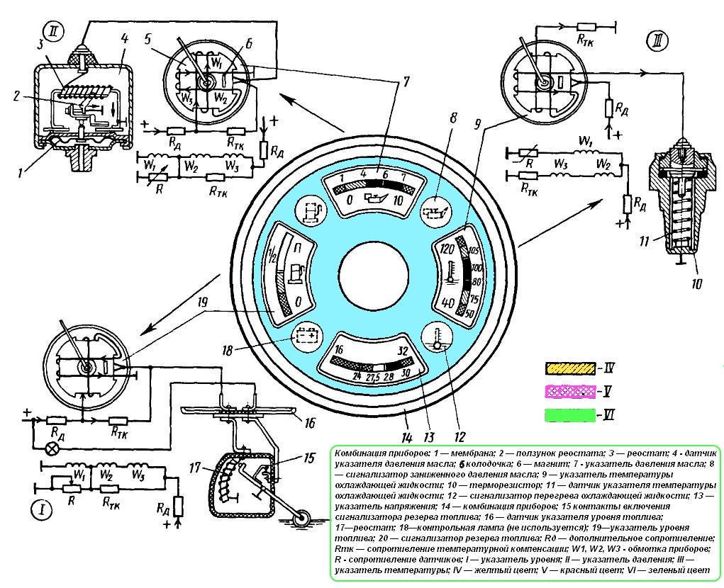
The car has two identical and independent indicators, made according to the scheme shown in fig. 118, c.
Depending on the air pressure, the sensor membrane bends, acting on the rheostat and changing the value of its resistance R. Otherwise, the operation of the needles does not differ from the operation of previously disassembled devices.
One of the pressure gauges shows the pressure in the car's receivers; the other, directly on the brake chambers when you press the brake pedal.

Rice. 118. Pointer schemes:
a is the water temperature; b - fuel level; c - air and oil pressure;
1 - sensor; 2 - pointer; 3 - permanent magnet; 4 - permanent disc magnet
Oil pressure indicator on the MAZ engine
The device is made according to the scheme shown in Fig. 118, c, and works similarly to an air pressure gauge.

Rice. 118. Pointer schemes:
a is the water temperature; b - fuel level; c - air and oil pressure;
1 - sensor; 2 - pointer; 3 - permanent magnet; 4 - permanent disc magnet
MAZ water temperature sensor
The water temperature indicator consists of a housing in which a plastic frame is mounted, on which windings K1, K2 and KZ are located (Fig. 118, a). A shaft is placed between the windings, on which a permanent disk magnet 4 and an arrow of the device are installed. A permanent magnet 3 is pressed into one of the corners of the frame. In the absence of current in the circuit, the fields of magnets 4 and 3 interact, and the arrow is in the leftmost position. When the current is turned on, the latter passes through the series-connected windings K2 and short-circuits the RTK resistor (temperature compensation resistance). In this case, the current passes through the coil K1 and through it through the semiconductor resistor R installed in the sensor housing 1 of the temperature indicator 2. The semiconductor resistor of the sensor changes its resistance depending on the temperature and thereby regulates the current strength in the circuit of the coil K1. Since the current strength does not change in coils K2 and short circuit, the position of the arrow of the device depends on the interaction of constant magnetic fields of coils K2 and short circuit with the coil field K1, which changes its value. The resulting field from all the coils places the magnetic disk 4 connected with the pointer in the desired position. The position of the device pointer depends on the interaction of the constant magnetic fields of the coils K2 and short circuit with the field of the coil K1, which changes its value. The resulting field from all the coils places the magnetic disk 4 connected with the pointer in the desired position. The position of the device pointer depends on the interaction of the constant magnetic fields of the coils K2 and short circuit with the field of the coil K1, which changes its value. The resulting field from all coils puts the magnetic disk 4 associated with the needle into position.
Read also KAMAZ and Skolkovo will create an environmentally friendly truck

Rice. 118. Pointer schemes:
a is the water temperature; b - fuel level; c - air and oil pressure;
1 - sensor; 2 - pointer; 3 - permanent magnet; 4 - permanent disc magnet
MAZ fuel level sensor
The fuel level indicator is designed and works similarly to the water temperature indicator (Fig. 118, b), with the only difference being that instead of a semiconductor resistor, a rheostat is built into the sensor, which changes its resistance depending on the position of the sensor floating in the tank.
In addition, an additional Rudd resistor was introduced into the K1 coil circuit, designed to limit the current in the coil when the sensor rheostat is turned off, which prevents overheating of the coil winding insulation.

Rice. 118. Pointer schemes:
a is the water temperature; b - fuel level; c - air and oil pressure;
1 - sensor; 2 - pointer; 3 - permanent magnet; 4 - permanent disc magnet