MAZ gearbox and its drive
During the operation of the car, it may be necessary to adjust the gearbox when various signs of malfunction appear. So, if gears IV and V are not included, and the rest are included, then the following is necessary:
- put alignment marks on the rod 10 (see Fig. 68) and tip 8;
- loosen the coupling bolts of the tie rod end 9 and turn the tie rod end 8 counterclockwise (when viewed along the vehicle) by 4-5°, which corresponds to a displacement of one mark relative to the other by about 1 mm;
- tighten the tightening screws 9 and check the meshing of the gears.
If necessary, additionally rotate the end of the rod.
If 1st and Reverse gears are not engaged, and all other gears are engaged, then the adjustment procedure is similar to that described above, except that the pin 8 must be turned clockwise (when viewed from the left) in the direction of the vehicle).
By touching the handle of lever 1 on the instrument panel or cab lid, make the following adjustments:
- put lever 1 in neutral position;
- disconnect the tip of the rod 10 from the earring 7 and make sure that the lever 2 is in the neutral position. The fork should be in a vertical position and rotational resistance should be felt during angular movement;
- fix the cross roller 13 of the intermediate control mechanism with the locking bolt 12 by fully screwing it into the tapered hole of the roller;
- using the spike 8, after loosening the coupling bolts 9, adjust the length of the rod 10 so that the pin 6 enters the hole of the fork of the spike 8 and the earring 7 freely, without additional movements to match the holes, and connect the tip with the earring, tighten the coupling bolts of the tip;
- loosen the locking bolt 12 by five turns and lock it with a nut.
Table 5
| Cause of failure | Resource |
| Increased heat transfer | |
| Faulty oil pump | Repair pump or replace |
| Insufficient oil level in the crankcase | Add oil to the required level |
| Noise increase | |
| Loosening the bolts that secure the clutch housing to the flywheel housing | Tighten the bolts |
| Shaft bearing wear | Replace bearings |
| Gear tooth wear | Replace gears |
| No change or hard change | |
| Worn synchronizer housing rings or separator breakage | Replace faulty synchronizers |
| Incomplete Disconnect | Adjust clutch pedal idle |
| High number of revolutions of the crankshaft of the engine idling | Adjust the number of revolutions of the crankshaft of the engine within 450-500 rpm |
| Lack of lubrication in the joints | Lubricate lubrication points |
| Automatic disengagement of gears when the car is moving | |
| Eliminate detent springs or seal sticking due to contamination of ball holes and springs | Clean dirty holes or replace broken springs |
| Worn clamping slots on shift fork stems | Replace rods |
| Significant wear of shift forks and synchronizer latches | Replace defective parts |
| Wear on the heads and tips of the gear lever and heads of the shift fork rod | Same |
| Worn or chipped teeth on gear couplings of carriages and synchronizer gears. Incomplete gearing. | Adjust the length of the shift mechanism rods; check the tightness of the shift fork bolts |
Note. After partial disassembly, the gearbox drive is adjusted in the same way as described above.
Possible malfunctions of the gearbox and ways to eliminate them are given in the table. 5.
MAZ gearbox repair
To determine the cause and eliminate a malfunction in the gearbox, it is rarely necessary to completely disassemble it. In some cases, to eliminate the malfunction, you can limit yourself to removing the gearbox cover, for which the remote control mechanism is first removed from the gearbox.
If the parts located in the gearbox housing need to be replaced or repaired, they must be removed from the vehicle. To do this, first of all, drain the oil from the gearbox, disconnect the propeller shaft from the gearbox, disconnect the clutch transmission rod from the gear lever cover and the clutch transmission rod from the gear lever, and remove the additional support from the gearbox. Substituting the lifting carriage under the gearbox housing, tighten the gearbox, unscrew the bolts securing the gearbox to the engine, disconnect the shaft from the gearbox drive shaft, lower the gearbox onto the cart.
In the future, to eliminate any malfunctions or replace individual parts, it is enough to disassemble the gearbox into individual components.
To disassemble the reducer, it is recommended to install it on a support with a turntable. Disassembly of the gearbox begins with the removal of the remote shift mechanism and the upper cover of the gearbox. When doing this, be careful not to damage the gaskets. Remove the release bearing cover from the propeller shaft, having previously disconnected the clutch lubrication hose and release springs from the fork. Remove the clutch release fork shaft by first unscrewing the pinch bolt and turning the shaft 180°. In this case, you can use a light touch. Using a universal puller, remove the driveshaft flange and puller bolts, driveshaft assembly cover with oil seal, and gasket.
By hitting the drive shaft with an aluminum hammer and shaking it by hand, the drive shaft assembly with bearing can be removed. To remove the driven shaft from the crankcase, you must first remove the rear bearing cover and use a puller to remove the rear bearing from the driven shaft, after removing the retaining ring.
The driven shaft assembly with gear is removed from the transmission case with pliers, removing the 1st gear and reverse gear from the splines.
The intermediate shaft is removed in the same way after removing the intermediate shaft rear bearing cover, thrust washer and intermediate shaft rear bearing. Then remove the oil pump and crankcase gasket from the housing.
To remove the gearbox with bearings and intermediate sleeve from the crankcase, you must first press the reverse gear shaft out of the crankcase using a puller.
The need for further disassembly of the gearbox is determined by external inspection.
Disassembly of the drive shaft is not difficult, since after removing the ring nut from the bearing, the latter is pressed out with a puller.
When disassembling the driven and intermediate shafts, it is first necessary to compress the bearings using universal pullers, and remove the retaining rings from the bearings and gears with special pullers.
For further disassembly of the driven shaft, the synchronizers of gears IV and V are removed. To remove the 5th gear from the shaft, the locking key is removed from the shaft spline. Then, turning the slot with a screwdriver, remove the thrust washer of the V-shaped gear. Under pressure from the side of the driven shaft of the gearbox, through the cartridge and the wooden clutch, the gear bushings are pressed in and the synchronizers, gears and synchronizers of II and III gears are removed.
The final disassembly of the intermediate shaft after removing the bearings and circlips is also done with a press or a universal puller.
First, the intermediate shaft drive gear is pressed in, then the gears of the V and III gears are pressed in, the spacer sleeve is removed, and, finally, the gear of the II gear is pressed in.
Disassembly of the gearbox cover with the gearshift mechanism, as well as the gearbox oil pump, usually does not cause much difficulty. After removing the gearbox assembly, wash the parts with kerosene or diesel fuel and blow them with compressed air.
An external examination reveals cracks, breaks, thread breaks, chipping and breakage of gear teeth and other damage.
In the presence of cracks or breakage of the teeth, as well as increased wear of the teeth, the gears are replaced.
The synchronizer can loosen bottom bracket clutch pins, bevel ring wear, bottom bracket teeth wear, and spline wear.
When the synchronizer carriage clutch is loosened, the unusable pins are drilled out and replaced with new ones with brass welding. The weld area is cleaned.
To determine the degree of wear of the bronze conical rings of the synchronizer cages, the conical surfaces of the corresponding gears that engage with it are used. When the ring is put on the gear, measure the gap between the end of the tooth and the synchronizer cage. The wear of the conical ring is considered within acceptable limits if the gap between the front face of the tooth and the support is at least 1,5 mm. Carriage tooth wear (along) on the shift side is allowed up to 8 mm. Cracks in the synchronizer cage are not allowed to be welded.
Assembly of nodes, as well as the final assembly of the gearbox, is carried out in the reverse order.
In this case, you should: Use the parts of the kit as much as possible. This is especially important for transmissions operating in quiet environments. However, when rejecting one of the mating parts, it is necessary to select the tightest fit on coincidences such as spline fits on synchronizer skids, 1st and reverse gears, bearings on shafts and in crankcases and other gaskets, and smooth running conditions on splined shafts are observed smooth rotation of the shafts and gears without jerking and jamming, etc.; when replacing the synchronizer or input shaft, as well as one of the gears of the driven shaft (except for 1st gear and reverse gear.
After assembly, all gearbox shafts should rotate easily and smoothly.
The gearbox is installed on the car in reverse order. After installing the box, check the clarity of shifting all gears.
MAZ gearbox maintenance
Maintenance of the gearbox consists in periodically checking the oil level and replacing it in the crankcase according to the instructions in the lubrication map. Oil is poured into the gearbox housing to the level of the control plug.
Read also Technical characteristics of the chassis and suspension of trailers GKB-8350, OdAZ-9370, OdAZ-9770
The oil must drain hot through both drain holes. There is a baffle in the oil pan, so it is impossible to pour all the oil through one hole. After draining the oil, remove the cover at the bottom of the crankcase, which contains the oil pump oil separator with a magnet, rinse them well and reinstall. In this case, it is necessary to ensure that the oil line is not blocked by the plug or its gasket.
To flush the gearbox, it is recommended to use 2,5-3 liters of bridge oil (GOST 1707-61). With the gearbox control lever in neutral position, crank the engine for 7-8 minutes, then stop, drain the oil from the spindle and fill the gearbox with the oil indicated in the lubrication card.
Since the gearbox has an oil pump, it is strictly forbidden to flush the gearbox with kerosene or diesel fuel, as insufficient suction vacuum can lead to its failure.
It must be remembered that the oil pump is driven from the intermediate shaft of the gearbox. Therefore, when the engine is not running, the oil pump does not supply lubrication to the driven shaft gear bearings or to the conical surfaces of the synchronizers. This is especially important to know when towing a vehicle with the engine off. In the case of towing the engine, it is necessary to disengage the clutch and engage IV gear (direct) in the box or disconnect the latter from the transmission, otherwise scratches may appear on the sliding surfaces and wear of the synchronizer rings. It is also necessary to check the reliability of fastening the top cover to the gearbox housing and the control mechanism to the top cover.
MAZ gearbox device
The MAZ gearbox (Fig. 66) is three-way, five-speed (with a fifth overdrive), with synchronizers in II, III and IV, V gears.
The gearbox housing 18 is attached to the clutch housing 4, and thus the engine, clutch and gearbox form a single power unit.
The drive shaft 2 is mounted on two bearings: in front, in the end hole of the engine crankshaft, and behind, in the front wall of the gearbox and bearing cap 3.
Grooves are cut into the front end of the drive shaft for mounting the clutch disc. In the rear part of the end of the shaft, which is included in the gearbox housing, a gear rim of constant mesh is cut. The shaft is fixed by axial movement in the bearing, which is fixed relative to the crankcase by a retaining ring included in the recess of the outer bearing ring, and, in addition, the inner ring of the bearing is pressed with a slotted nut. The inner hole of the gear rim of the drive shaft is the front support for the driven shaft 14, mounted on a cylindrical roller bearing, the rear end of the driven shaft rests on a ball bearing, fixed with a retaining ring in the crankcase wall and cover 15.
The driven shaft is a splined shaft of variable cross section. Installed in series (from front) with 5-speed synchromesh IV and V, 8-speed synchromesh V, 9-speed III, 10-speed synchromesh II and III, 11-speed synchromesh II gear and gear 12 I and reverse gear.
The synchronizer carriage of gears IV and V is mounted on the splines of the shaft, and the gears II and III are mounted on a sleeve with a splined outer surface, fixed relative to the shaft with keys. The gears of II, III and V gears of the driven shaft are mounted in plain bearings made in the form of steel bushings with a special coating and impregnation. 1st gear and reverse gear can move along the splined section of the driven shaft. The axial movement of the remaining gears is limited by thrust washers and spacers.
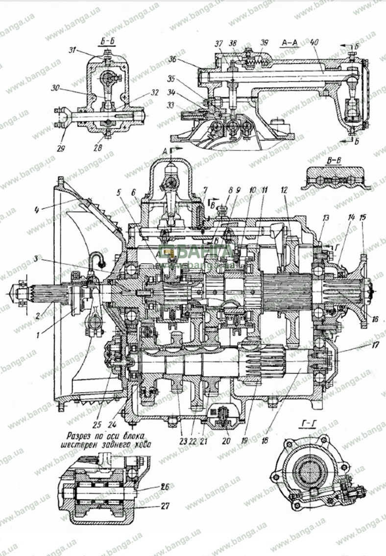
Rice. 66. Gearbox YaMZ-236:
1 - clutch release clutch; 2 - drive shaft; 3 — a cover of the bearing of an input shaft; 4 - clutch housing; 5 - synchronizer of IV and V gears; 6 - gear lever; 7 - ball retainer with a spring; 8 - driven shaft of the wedge-shaped transmission; 9 - gear wheel of the third gear of the driven shaft; 10 - synchronizer gears II and III; 11 - gear of the second gear of the driven shaft; 12 - gear 1st gear and reverse gear of the driven axle; 13 — the top cover of a transmission with a rod and plugs; 14 - driven shaft; 15 - bearing cover of the driven shaft; 16 - flange for fastening the cardan shaft to the gearbox; 17 - intermediate shaft with 1st gear; 18 - gearbox; 19 - sprocket of the second gear of the intermediate shaft; 20 — an input of the oil pump with a magnet; 21 — an asterisk of the III gear wheel of an intermediate shaft; 22 - intermediate shaft V-shaped transmission; 23 - power take-off; 24 - intermediate shaft drive gear; 25 - oil pump; 26 - reverse block shaft; 27 - reverse block; 28 — a rod of a fork of longitudinal draft; 29 - intermediate gear lever; 30 - crankcase mechanism for remote gear shifting; 31 - bar for switching 1st gear and reverse gear; 32 - spring-loaded reversible fuse; 33 — pin of the lock of a choice of transfers with a spring; 34 - gear shift shaft; 35 - speedometer drive gear worm 31 - 1st gear and reverse gear engagement belt; 32 - spring-loaded reversible fuse; 33 — pin of the lock of a choice of transfers with a spring; 34 - gear shift shaft; 35 - speedometer drive gear worm 31 - 1st gear and reverse gear engagement belt; 32 - spring-loaded reversible fuse; 33 — pin of the lock of a choice of transfers with a spring; 34 - gear shift shaft; 35 - worm gear speedometer drive
The front end of the intermediate shaft 17 is supported by a roller bearing mounted on the front wall of the gearbox housing, and the rear end is supported by a ball bearing fixed with a retaining ring on the wall and the crankcase cover. Also, the rear end of the intermediate shaft is attracted to the inner race of the bearing with a washer and two bolts screwed into the end of the shaft.
The intermediate shaft, in addition to the splined rear, which is the ring gear of the 1st and reverse gears, has a smooth stepped surface with a number of grooves for the pinion locking keys. On the intermediate shaft are sequentially located: gear 24 of constant clutch, gear 23 of power take-off through the side hatch, gear 22 V of the gearbox and gear 21 of gear III, spacer and gear 19 of gear II.
At the front end of the intermediate shaft, a groove is made to drive the roller 25 of the oil pump.
In the tides of the gearbox housing, an additional shaft 26 is installed, on which a block 27 of the reverse intermediate gear is mounted on two roller bearings. One of the gears of the block is in constant contact with the ring gear of the intermediate shaft of the 1st gear; the other gear engages with the 1st gear, which slides over the splines of the output shaft when moving backwards when reverse is engaged.
All transmission gears, except 1st, reverse and PTO gears, are in constant mesh with the corresponding gears on the drive and driven shafts, have helical teeth to reduce gear noise and increase gear durability.
Gearbox gear teeth are lubricated from below the crankcase. The sleeve, which performs the function of bearings for the gears of the driven shaft, is lubricated with oil under pressure from the oil pump 25, mounted on the front wall of the crankcase. The pump is driven from the end of the intermediate shaft of the gearbox.
The protruding end of the oil pump drive shaft has two flats that fit into a matching groove on the end of the intermediate shaft of the transmission. The oil pump drive gear is fixed on the roller with a key; its driven gear sits freely on the shaft. Oil from the channel in the crankcase wall and communicating with the sump, protected by a filter mesh, enters the pump.
As the gears rotate, there is suction where the teeth disengage and pressure on the side where they engage. Through the channel, the oil exits the pump into the discharge line.
To avoid overloading parts, the pump has a bypass ball valve that connects the pump discharge to the suction when the oil pressure is too high.
Through a channel in the front wall of the crankcase and a channel in the cardan shaft cover, oil enters the radial channels of the cardan shaft. Of these, through the axial channel of the input shaft and the adapter sleeve, oil is supplied to the axial channel of the driven shaft, and then through the radial holes to the toothed bushings of gears V, III and II.
To clean the oil in the lower part of the crankcase there is an oil receiver with a magnetic plug.
The described gearbox is made according to a scheme in which the corresponding gears of all gears, except for I and reverse, are in constant engagement. With such a kinematic scheme, it is more convenient and easier to shift gears using synchronizers that provide silent and shock-free engagement of gears, which increases the durability of gearbox parts.
The synchronizer (Fig. 67) consists of the following main parts: clutch 5, carriage 6 and clip 7.
The synchronizer carriage is a hollow cylinder with four evenly spaced longitudinal through slots on the surface. The grooves have a special configuration: in the central part they expand to a certain length and have a beveled exit. Along the edges, the slots are made even wider, but with a gentle rounding to eliminate stress concentration along the edges of the clip. The clip is a very responsible and loaded part, so it is made of high quality steel and subjected to heat treatment in the groove area.
Read also KamAZ suspension service
The grooves of the holder include four processes of the synchronizer carriage, in which the coupling is fixed. The synchronizer carriage also has four equidistant holes around the circumference, into which 12 balls with spring clips are inserted.
In the middle neutral position, the cage is connected to the carriage by means of spring clips, the balls of which, under the action of the springs, enter the corresponding grooves of the cage. Bronze conical rings 3 and 8 are riveted to both ends of the synchronizer cage. There is a slotted hole in the synchronizer carriage. In the synchronizer of the V and IV gears, the carriage slides along the splines of the driven shaft 1, and in the synchronizer of the III and II gears, along the slots of the spacer sleeve of the gears of the III and II gears. Gear couplings 10 and 13 are cut off at both ends of the hub of the synchronizer carriage.
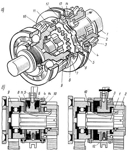
Rice. 67. Synchronizer:
to - in context; b - scheme of work; 1 - driven shaft of the gearbox; 2 - V-shaped transmission; 3 — a conical ring of the synchronizer of inclusion of a V-shaped transfer; 4 - conical crown of the V-shaped drive; 5 - clutch of inclusion of IV and V gears; 6 - synchronizer carriage; 7 - support of conical rings; 8 — conical ring of inclusion of the IV transfer; 9 - drive shaft of the gearbox; 10 - clutch of the gear of the synchronizer carriage of the IV gear; 11 and 14 - gear couplings; 12 - ball bearing of the carriage; 13 - clutch of the synchronizer carriage gear for engaging the V-shaped gear
When the gear is engaged, the connecting rod fork moves the clutch 5 to engage gears IV and V in the appropriate direction, which moves the corresponding carriage and synchronizer cage along the shaft. When the cage body ring is pressed against the gear cone, the speed changes, as a result of which the rectangular processes of the carriage included in its grooves are displaced and enter the recesses on the middle side of the cage grooves.
Until the mutual sliding of the conical surfaces stops and the speeds of the cage and the gear are equal, further movement of the carriage along the axis of the shaft is impossible.
After equalizing the speeds of rotation of the cage and the gear, the processes of the carriage will no longer be pressed against the recesses on the middle side of the splines and the coupling will be able to move along the axis of the shaft. When the clutch is moved under the action of the gear shift fork, the balls connecting the carriage with the cage will come out of the groove of the latter, the carriage will move along the y-axis, since it rotates simultaneously with the speed when the gear is engaged, the gear clutch of the carriage will enter without impact and noise, engaging with the gear clutch (locked).
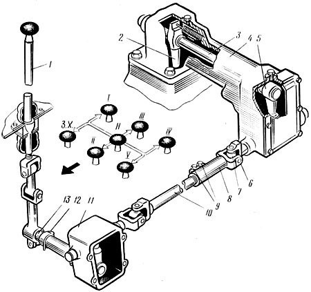
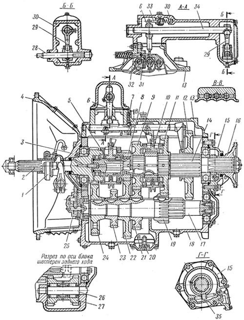
Rice. 68. Gearbox MAZ:
1 - gearshift lever; 2 - lever of the switching mechanism; 3 - gear shift roller; 4 - crankcase of the mechanism of remote gear shifting; 5 - intermediate gear lever; 6 - finger; 7 - hinged earring; 8 - thrust tip; 9 - coupling bolts; 10 - thrust; 11 - intermediate mechanism; 12 - locking bolt; 13 - cross roller
When the gear is engaged, the engine torque is transmitted through the flywheel, pressure and friction discs to the input shaft of the gearbox, and from its ring gear to the mating gear of the intermediate shaft and then, along the torque, the gears corresponding to the engaged gear, to the synchronizer carriage and to the secondary shaft of the gearbox . Only in 1st gear and reverse gear is the torque transmitted directly from the intermediate shaft of the gearbox. Since there is no 1st gear synchronizer, shift to 1st gear only after a significant reduction in speed to avoid gear damage.
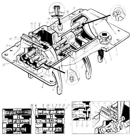
Rice. 69. MAZ gearbox cover:
1 - top cover; 2 - cork; 3 - switch fork of the 4st transmission and reverse gear; 5 — a fork of switching of II and III transfers; 10 — a rod of a fork of switching of IV and V transfers; in and 7 - sockets; 8 - rod lock balls; 9 — a fork of switching of IV and V transfers; 11 - locking bolt; 12 — a head of a rod of a plug of switching of the I transfer and a backing; 13 - fusible spring; 14 - spring vessel; 15 - belt axis; 1 - bar for engaging 16st gear and reverse gear; 17 - reverse gear fuses; 18 — a head of a rod of a plug of switching of II and III transfers; 19 - locking ball; 20 - retaining spring; 21 — a rod of a fork of switching of II and III transfers; 22 — a rod of a fork of switching of the I transmission and a backing; 23 — the lever of the mechanism of remote gear change; XNUMX - stem locking pin.
The location of the gearbox, quite far from the driver, led to the need for a remote gearbox control unit. The control panel (Fig. 68) consists of a gear shift mechanism located directly on the gearbox, and a system of rods and levers connected to gear shift lever 1 installed in the cab.
Three rods are installed on the tides of the upper cover 1 (Fig. 69) of the gearbox.
Gearshift forks are attached to each linkage. On the extreme right rod (in the direction of the car) there is a fork 3 for shifting 1st gear and reverse gear, on the middle rod there is a fork 4 for shifting II and III gears and on the third rod there is a fork of 8th and 3rd gears change Gears IV and V.
To ensure a strict position on the stem, each fork is held by a fixed locking screw, which, with its conical end, enters the same hole in the stem. To prevent the screw from getting out, it is attached with a cotter pin to the fork. The forged steel forks feature carefully engineered heat-treated jaws that fit into an annular groove on the shifter sleeve.
The rods 5, 20 and 21 move in the guide supports of the top cover using the lever 22 of the remote switching mechanism. On the shaft of the 1st gear and reverse, as well as on the shift lever of the 2nd and 3rd gears, there are heads (respectively 11 and 17).
The lever 22 enters directly into the head 17 and the lever 11 enters the head 11 through the belt 15 for shifting first gear and reverse gear.
To engage gears IV and V, the lever 22 can enter directly into the groove of the fork 8 to shift these gears. The position of the 1st gear and reverse shaft is fixed in the cover with the help of fuses 16 included in the bar 15 under the action of the spring 12 placed in the glass 13. Only after overcoming the force of the spring of this fuse, you can turn on the pers-dacha or vice versa. In addition, there are rod clamps made in the form of 18 balls with springs.
The rods have three holes for balls. The balls of the retainers under the action of the springs enter these grooves and fix the rods in the position corresponding to the inclusion of a certain gear, as well as in the neutral position. To exclude the possibility of simultaneous engagement of two different gears due to the joint movement of two connecting rods, a lock is provided, which, when one of the connecting rods moves, blocks the other two in the neutral position. To do this, a channel was drilled in the partition of the upper cover of the gearbox, into which two balls 7 were inserted between the rods. Recesses for balls were made in the rods; in addition, there is a hole in the central bar into which the pin 23 of the rod lock is inserted. moving the central rod.
If one of the extreme rods moves, then the ball comes out of the recess and, pressing on the neighboring ball, moves the pin of the central rod in such a way that it presses on the other two balls, one of which enters the recess of the second extreme rod, blocking this and half drain.
On the top cover of the gearbox there is a crankcase (see Fig. 66) of the gearbox remote control mechanism, on which the gear shift shaft 34 is located with the lever 6 fixed on it, which controls the gear shift rod, and the intermediate lever 29 is connected to the longitudinal rod of the remote control.
In the crankcase of the remote mechanism there is also a pin 33 of the gear selector latch, which is pressed against the lever 6 by a spring located in the hole in the crankcase and holds it in the neutral position. At the outer end of the cantilever part of the crankcase in the tides, supports are made for the rod 28 of the yoke of the longitudinal thrust. On the rod 28, a head is fixed, which includes the head of the lever 29.
The connecting rod 28 of the fork of the longitudinal stop in its bearings can perform both longitudinal and angular movement. The angular movement of the rod 28 causes the longitudinal movement of the axis 34, which leads to the connection of the lever 6 located on it with a certain slider in the upper cover of the gearbox. The longitudinal movement of the rod 28 of the longitudinal fork leads to the rotation of the shaft 34 of the gear lever and the lever 6 sitting on it.
The presence of hinges and a ball joint provides the ability to tilt the cab without disturbing the neutral position of the gearbox control lever. In this case, the ball joint of the lever, connected to the base of the cabin, slides along the lever rod.
When the cab is lowered, a clear kinematic connection is determined throughout the remote drive between each element of the gearbox control gear mechanism.