P000D B Camshaft Position Slow Response Bank 2
Content
- P000D B Camshaft Position Slow Response Bank 2
- OBD-II DTC Datasheet
- What does this mean?
- What is the severity of this DTC?
- What are some of the symptoms of the code?
- What are the possible causes of the code appearing?
- What are some steps to troubleshoot the P000D?
- Related DTC discussions
- Need more help with your P000D code?
P000D B Camshaft Position Slow Response Bank 2
OBD-II DTC Datasheet
B Camshaft position, slow response bank 2
What does this mean?
This Generic Transmission Diagnostic Trouble Code (DTC) typically applies to all OBD-II vehicles equipped with a variable valve timing / cam system. This may include, but is not limited to, Subaru, Dodge, VW, Audi, Jeep, GMC, Chevrolet, Saturn, Chrysler, Ford, etc. Despite the general nature, the exact repair steps may vary depending on the make / model. ...
Many modern cars use Variable Valve Timing (VVT) to improve engine performance and fuel economy. In the VVT system, the powertrain control module (PCM) controls the oil control solenoid valves. These valves supply oil pressure to an actuator mounted between the camshaft and the drive chain sprocket. In turn, the actuator changes the angular position or phase change of the camshaft. The camshaft position sensor is used to monitor the position of the camshaft.
The camshaft position slow response code is set when the actual camshaft position does not match the position required by the PCM during camshaft timing.
As far as the description of the trouble codes, "A" stands for intake, left or front camshaft. On the other hand, "B" stands for exhaust, right or rear camshaft. Bank 1 is the side of the engine that contains cylinder #1, and bank 2 is the opposite. If the engine is inline or straight, then there is only one roll.
Code P000D is set when the PCM detects a slow response when changing the phase of the camshaft position from circuit “B” bank 2. This code is associated with P000A, P000B and P000C.
What is the severity of this DTC?
The severity of this code is moderate to severe. It is recommended to fix this code as soon as possible.
What are some of the symptoms of the code?
Symptoms of a P000D trouble code may include:
- Check Engine Light
- Increased emissions
- Poor engine performance
- Engine noise
What are the possible causes of the code appearing?
Reasons for this code may include:
- Incorrect oil supply
- Defective camshaft position sensor
- Defective oil control valve
- Defective VVT drive
- Timing chain problems
- Wiring problems
- Defective PCM
Example of a camshaft position (CMP) sensor: 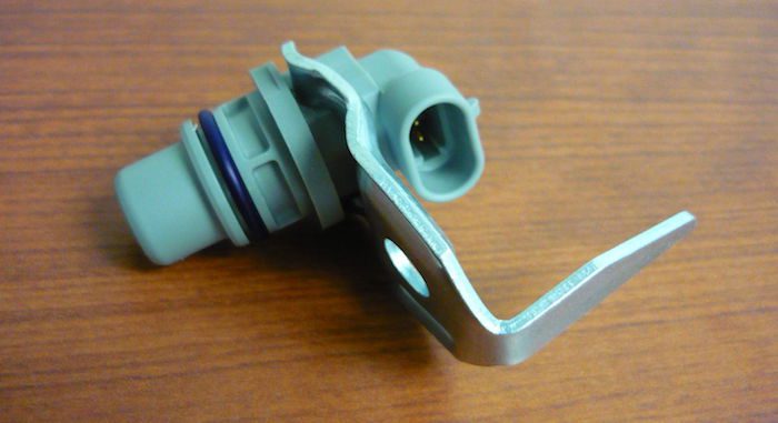
What are some steps to troubleshoot the P000D?
Start by checking the level and condition of the engine oil. If the oil is normal, visually inspect the CMP sensor, oil control solenoid and associated wiring. Look for loose connections, damaged wiring, etc. If damage is found, repair as needed, clear the code and see if it returns. Then check the technical service bulletins (TSBs) for the problem. If nothing is found, you will need to proceed to the step-by-step system diagnostics.
The following is a generalized procedure as the testing of this code differs from vehicle to vehicle. To accurately test the system, you need to refer to the manufacturer's diagnostic flowchart.
Before proceeding, you need to consult the factory wiring diagrams to determine which wires are which. Autozone offers free online repair guides for many vehicles and ALLDATA offers a one-car subscription.
Check the camshaft position sensor
Most of the camshaft position sensors are Hall or permanent magnet sensors. There are three wires connected to the Hall effect sensor: reference, signal and ground. On the other hand, a permanent magnet sensor will only have two wires: signal and ground.
- Hall sensor: Determine which wire is the signal return wire. Then connect a digital multimeter (DMM) to it using the test lead with the back probe. Set the digital multimeter to DC voltage and connect the meter's black lead to chassis ground. Crank the engine - if the sensor is working properly, you should see fluctuations in the readings on the meter. Otherwise, the sensor is defective and must be replaced.
- Permanent Magnet Sensor: Remove the sensor connector and connect a DMM to the sensor terminals. Set the DMM to AC voltage position and crank the engine. You should see a fluctuating voltage reading. Otherwise, the sensor is defective and must be replaced.
Check sensor circuit
- Hall sensor: start by checking the grounding of the circuit. To do this, connect a DC-set DMM between the positive terminal on the battery and the sensor ground terminal on the harness side connector. If there is a good ground connection, you should get a reading of about 12 volts. Then test the 5-volt reference side of the circuit by connecting a digital multimeter set to volts between the negative battery terminal and the reference terminal of the sensor on the harness side of the connector. Turn on the car ignition. You should see a reading of about 5 volts. If neither of these two tests gives a satisfactory reading, the circuit needs to be diagnosed and repaired.
- Permanent magnet sensor: check circuit ground. To do this, connect a DC-set DMM between the positive terminal on the battery and the sensor ground terminal on the harness side connector. If there is a good ground connection, you should get a reading of about 12 volts. Otherwise, the circuit will need to be diagnosed and repaired.
Check Oil Control Solenoid
Remove the solenoid connector. Use a digital multimeter set to ohms to check the internal resistance of the solenoid. To do this, connect a meter between the B + solenoid terminal and the solenoid ground terminal. Compare the measured resistance with the factory repair specifications. If the meter shows an out-of-specification or out-of-range (OL) reading indicating an open circuit, the solenoid should be replaced. It's also a good idea to remove the solenoid to visually inspect the screen for metal debris.
Check the oil control solenoid circuit
- Check the power section of the circuit: Remove the solenoid connector. With the vehicle ignition on, use a digital multimeter set to DC voltage to check for power to the solenoid (usually 12 volts). To do this, connect the negative meter lead to the negative battery terminal and the positive meter lead to the solenoid B+ terminal on the harness side of the connector. The meter should show 12 volts. Otherwise, the circuit will need to be diagnosed and repaired.
- Check circuit ground: Remove solenoid connector. With the vehicle ignition on, use a digital multimeter set to DC voltage to check for grounding. To do this, connect the positive meter lead to the positive battery terminal and the negative meter lead to the solenoid ground terminal on the harness side of the connector. Command the solenoid on with an OEM equivalent scan tool. The meter should show 12 volts. If not, the circuit will need to be diagnosed and repaired.
Check timing chain and VVT drives.
If everything passes up to this point, the problem may be in the timing chain, the corresponding drives or VVT drives. Remove the required components to gain access to the timing chain and actuators. Check the chain for excess play, broken guides and / or tensioners. Check the drives for visible damage such as tooth wear.
Related DTC discussions
- Challenger 2011 P0135 P000DThe car engine shakes violently, goes out….
Need more help with your P000D code?
If you still need help regarding DTC P000D, post a question in the comments below this article.
NOTE. This information is provided for informational purposes only. It is not intended to be used as a repair recommendation and we are not responsible for any action you take on any vehicle. All information on this site is protected by copyright.