Cherry tiggo fuses
Content
The fuse and relay mounting block (block) is located in the engine compartment (OS)
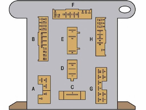
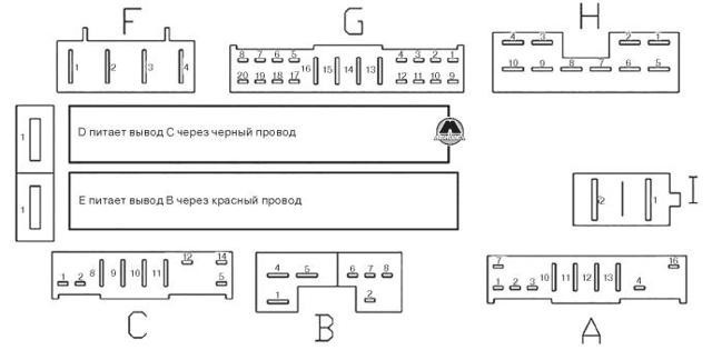
Scheme 1. The order of conditional numbering of contacts in the block of the mounting block of fuses and relays located in the engine compartment (OU) (for the location and ratings of the fuses, see the "Mounting blocks" subsection).
The fuse and relay mounting block is located (block) under the instrument panel (UV)
Scheme 2. According to the conditional numbering of the contacts on the block of the fuse and relay mounting block located under the instrument panel (UV) (for the location and classification of the fuses, see the "Mounting blocks" subsection).
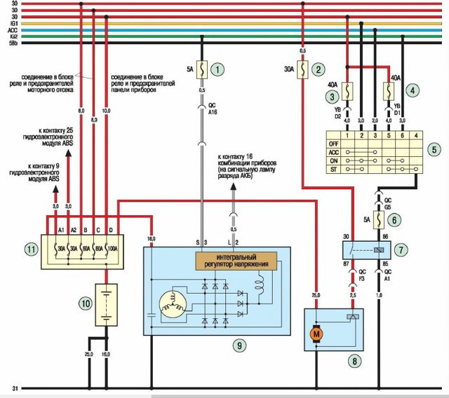
Scheme 3. System for starting the engine and charging the battery: 1,2, 3, 4, 6 - fuses; 5 - power switch (lock); 7 - starter relay; 8 - starter; 9 - generator; 10 - battery; 11 - additional fuse box
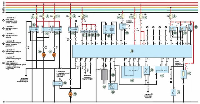
4 schema.
Electronic engine management system: 1-9 - fuses; 10 - ignition coil; 11 - diagnostic oxygen concentration sensor; 12 - oxygen concentration control sensor - adsorber purge solenoid valve; 14 - ECU; 15 - vehicle speed sensor; 16 - power steering switch; 17 - throttle position sensor; 18 - coolant temperature sensor; 19 - idle valve; 20 - knock sensor; 21 - sensor wiring harness screen; 22 - crankshaft position sensor; 23 - electric fuel pump; 24 - relay of the main cooling fan; 25 - additional cooling fan; 26 - main cooling fan; 27 - temperature sensor; 28, 29, 30, 31 - nozzles; 32 - electric fuel pump relay
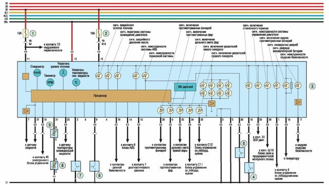
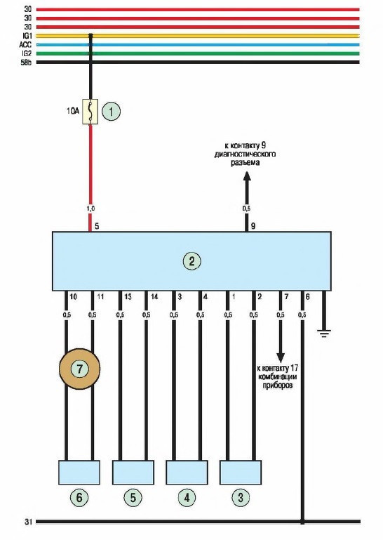
Scheme 5. Instrument panel: 1.2 - fuses; 3 - instrument panel; 4 — the switch of an alarm lamp of a parking brake; 5 - brake fluid level indicator sensor; 6 - pressure sensor of the coolant level analyzer; 7 - coolant level indicator sensor; 8 - additional fuel level sensor; 9 - fuel level sensor
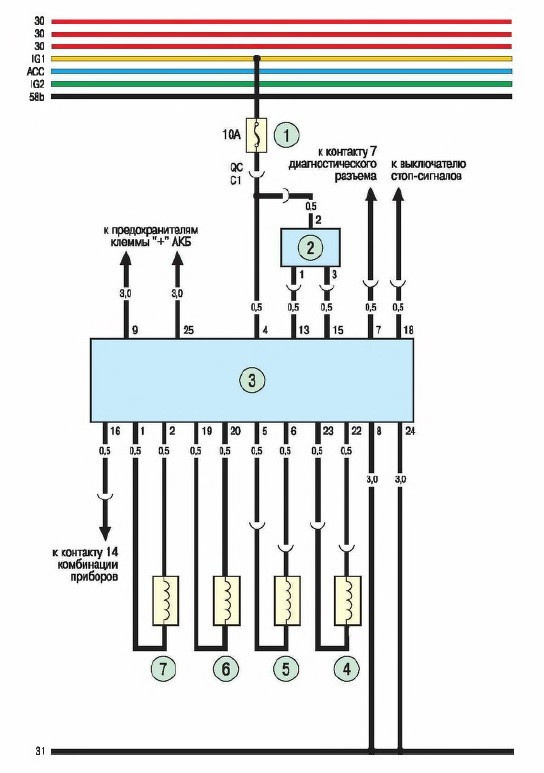
Scheme 6. Passive safety system: 1 - fuse; 2- electronic control and diagnostic unit; 3 - driver's seat belt pretensioner; 4 - front passenger seat belt pretensioner; 5 - passenger airbag module; 6 - driver airbag module; 7 - swivel connector on the steering column
Scheme 7. Anti-lock braking system (ABS): 1 - fuse; 2- deceleration sensor; 3- hydroelectronic block; 4-sensor of the right rear wheel; 5-sensor rear left wheel; 6 - right front wheel sensor; 7 - front left wheel sensor
8 schema.
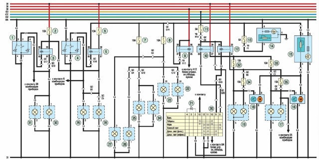
Exterior and interior lighting of the car: 1 - rear fog lamp switch; 2, 6, 7, 8, 11, 13 - fuses; 3 - rear fog lamp relay; 4 - fog lamp relay; 5 - fog lamp switch; 9 — the relay of lamps of dimensional lights; 10 - low beam relay; 12 - high beam relay; 14 - brightness control of the instrument cluster backlight; 15 - headlight electrocorrector regulator; 16 - electric corrector of the right headlight; 17 - block headlight right; 18 — electric corrector of the left headlight; 19 — headlight of the left block; 20 - outdoor lighting switch; 21 - illumination of the light signal switch; 22, 23 - front marker lights; 24, 25 - license plate lights; 26, 27 - rear lights; 28, 29 — fog lights; 30, 31 - rear fog lamp
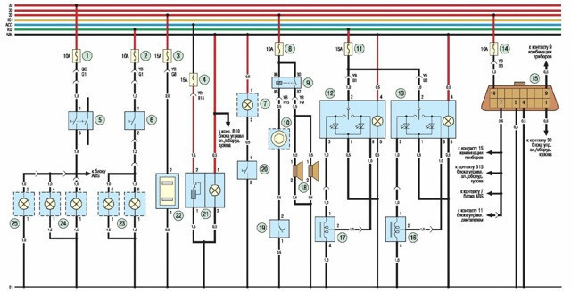
- Scheme 9. Sound and light alarm, electric seat heating and diagnostic connector: 1, 2, 3, 4, 8, 11, 14 - fuses; 5 - stoplight switch; 6 - backup switch; 7 - ashtray lighting; 9 - retransmission of sound signals; 10 - swivel connector; 12 - switch for heating the driver's seat; 13 - passenger seat heating switch; 15 - diagnostic connector; 16- passenger seat heating element; 17 - driver's seat heating element; 18 - sound signals; 19- sound signal switch; 20 - ashtray backlight switch; 21 - lighting 22 - socket for additional electrical appliances; 23 - reversing lights; 24 - brake lights; 25 - additional brake light
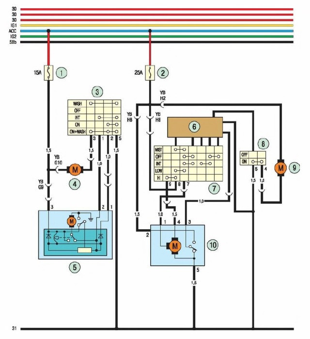
 Scheme 10. Windshield wipers and washers of the windshield and rear window: 1.2 - fuses; 3 — the switch of a screen wiper of a back door; 4 — the electric motor of a washer of glass of a back door; 5 - rear door wiper motor reducer; 6 - wiper control relay; 7 — the switch of a screen wiper and a washer; 8 - contacts of the windshield washer switch; 9 - windshield washer gear motor, wiper gear motor
- Scheme 11. Electric drive of external rear-view mirrors: 1 - remote control for side rear-view mirrors; 2 - fuse; 3 — the right external rear-view mirror; 4 — the left external rear-view mirror
- Scheme 12. Body electrical control unit: 1 - lamp for lighting the front of the cabin; 2 — a lantern of illumination of the central part of salon; 3 — a lantern of illumination of a back part of salon; rear door glass heating switch; 5, 6, 7, 8, 12, 13 - fuses; 9 - ignition switch illumination lamp; 10 - sensor for the presence of a key in the ignition lock; 11 - alarm signaling device - motor-reducer of the front left door lock drive; 15 - motor reducer of the lock drive of the right front door; 16 - motor reducer of the lock drive of the rear left door; 17 - motor-reducer of the lock drive of the right rear door; 18 - motor-reducer of the tailgate lock drive; 19 - open door alarm switch; 20 - alarm switch; 21 - electrical control unit 22, 23, 24 - starboard direction indicators; 25, 26, 27 - lights of the left side direction indicator; 28 - light switch in the left front door; 29 - light switch on the right side of the door; 30 - light switch on the tailgate; 31 - warning buzzer; 32 - switch for the indicator of the unfastened seat belt buckle; 33 - tailgate opening switch; 34 - pamp of an open door signaling device; 35 - switch to open the right front door; 36 - switch for opening the left rear door; 37 - switch for opening the right rear door; 38 - signal lamp of the open door tsoa; 39 - switch for opening the left front door; 40 - element for heating the glass of the rear door 32 - switch for the indicator of an unfastened seat belt buckle; 33 - tailgate opening switch; 34 - pamp of an open door signaling device; 35 - switch to open the right front door; 36 - switch for opening the left rear door; 37 - switch for opening the right rear door; 38 - signal lamp of the open door tsoa; 39 - switch for opening the left front door; 40 - element for heating the glass of the rear door 32 - switch for the indicator of an unfastened seat belt buckle; 33 - tailgate opening switch; 34 - pamp of an open door signaling device; 35 - switch to open the right front door; 36 - switch for opening the left rear door; 37 - switch for opening the right rear door; 38 - signal lamp of the open door tsoa; 39 - switch for opening the left front door; 40 — a heating element of glass of a door of a back
- Scheme 13. Electric drives of the side windows of the car: 1 - the central control unit for electric windows; 2 — the switch of management of a window regulator of a forward right door; 3- power window switch of the rear left door; 4 — the switch of management of an electrowindow regulator of the right back door; 5 - body electrical control unit; 6 - power window of the right rear door; 7 - motor-reducer window lifter left rear door; 8 - gearmotor of the power window of the right front door; 9 — the motor-reducer of a window regulator of the left forward door
- Scheme 14. Ventilation, heating and air conditioning systems: 1, 2, 3, 4 - fuses; 5 - relay for controlling the electric motor of the passenger compartment fan; 6 - switch for the intensity of air supply to the passenger compartment; 7 - additional resistors; 8 - internal fan motor; 9 — the relay of the electric motor of the fan of salon; 10 - electromagnet of the clutch for turning on the air conditioning compressor; 11 - fuse; 12- relay for switching on the compressor; 13 - combined pressure sensor; 14 - air conditioner switch; 15 - air recirculation damper gear motor
- Scheme 15. Sliding roof electric drive: 1.2 - fuses; 3 — the switch of the electric drive of the hatch of a roof; 4 - electric sliding roof
- Scheme 16. Car radio: 1,2 - fuses; 3 - car radio; 4, 5, 6, 7 - speakers
 Scheme 10. Windshield wipers and washers of the windshield and rear window: 1.2 - fuses; 3 — the switch of a screen wiper of a back door; 4 — the electric motor of a washer of glass of a back door; 5 - rear door wiper motor reducer; 6 - wiper control relay; 7 — the switch of a screen wiper and a washer; 8 - contacts of the windshield washer switch; 9 - windshield washer gear motor, wiper gear motor
- Section 1. Vehicle device
- Section 2. Vehicle Operation Tips
- Section 3. Breakdowns in transit
- Section 4 Maintenance
- Section 5 Engine
- Section 6 Transfer
- Section 7 Chassis
- Section 8. Address
- Section 9. Braking system
- Section 10. Electrical equipment
- Section 11 Body
- Section 12
- Section 13 Security system
- Section 14. Wheels and tires
- Applications
- Electrical diagrams
Fuses and relay Chery Tiggo

Where are the fuses.
See also: Popular question: Which engine is better in the Audi A6 C7?
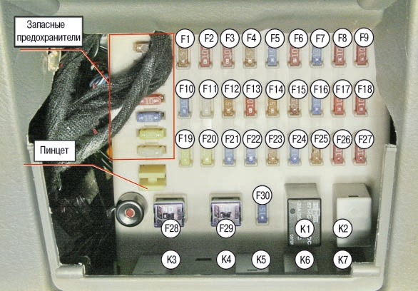
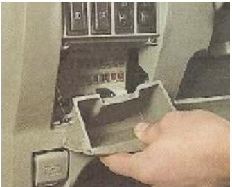
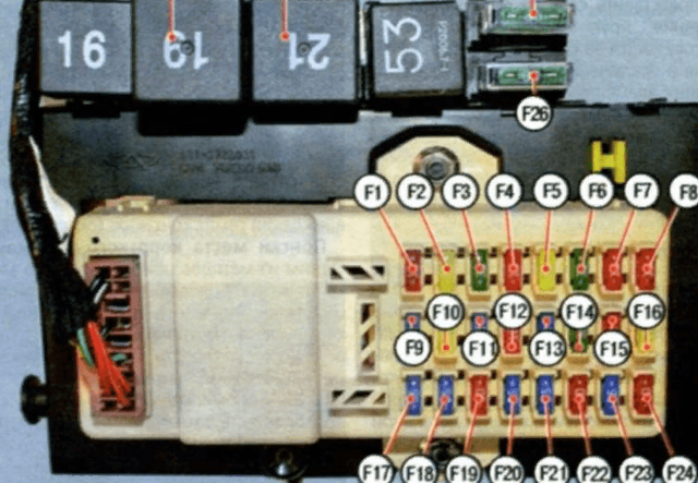
In the cabin on the left side of the dashboard under the box for small items. To access, open the drawer and pull up.
Spare fuses and clips are located in special sockets.
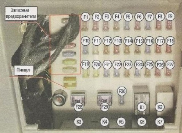
Deciphered:
F1- Instrument lighting control F2 - Lambda probe (lambda probe), fuel tank valve, speedometer. F3 - Power supply to the engine injector.
F4 - Air conditioning button F5 - Cigarette lighter F6 - Dashboard illumination power supply F7 - Permanent tape recorder power supply F8 - Diagnostic connector Terminal 16 F9 - Dashboard power supply F10 - Rear wiper F11 - Front wiper F12 - Low and high beam relay (coil) F13 - Cushion F14 - Radio (adaptive cruise control) F15 - Mirrors F16 - Heated seats F17 - Engine control unit power supply (1st contact) F18 - Alarm and lock control module F19 - Power windows F20 - Sunroof (engine) module power supply F21 - Off button F22 - Interior lighting, door lighting, open door indicator F23 - Sunroof control button F24 - Horn F25 - Cabin air recirculation damper (button and motor) F26 - Air conditioning relay (winding) F27 - Rear-view mirrors F28 - AM1 ( through the ignition switch goes to the ACC and IG1 lines) F29 - AM2 (through the ignition switch goes to the IG2 line and the starter relay winding)
F30 - reserved
- Relay K1 - Fan Relay K2 - Spare K5 - Horn Relay K6 - Turn Signal Relay
- K7 - Air conditioner relay
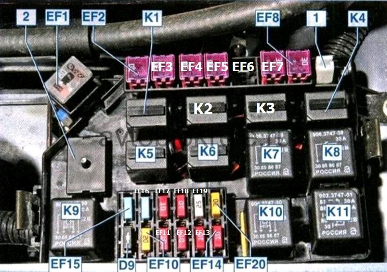
- Mounting block fuses and relays in the engine compartment
- To access the fuses, unscrew the screws that hold the block cover
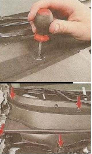
Plug the latch core and remove it from the hole
Then, with great force, disconnect the rubber seal of the air intake box from the compartment cover of the mounting block
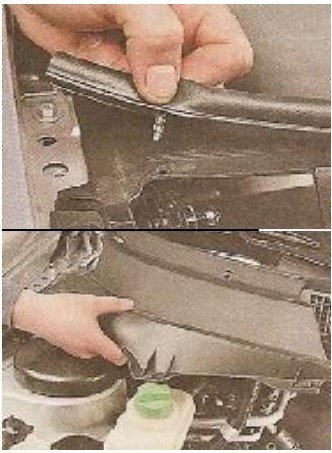
Then press the latch and remove the mounting block cover
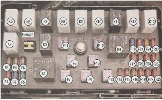
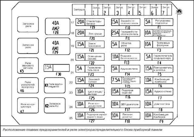
On the inside of the cover there is a diagram of the location of the fuses and relays.
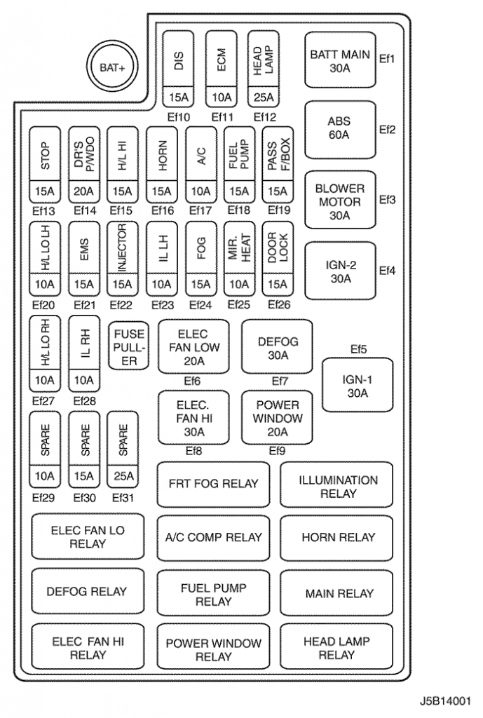
- Deciphered:
- 1 - Low beam (left lamp) 2 - Low beam (right lamp) 3 - Fuel pump (relay contacts) 4 - High beam (left lamp) 5 - Interior fan motor 6 - High beam (left lamp) right) 7 - Electric motor relay for cooling and air conditioning engines No. 2 (contacts) 8 - Relay for cooling and air conditioning engines No. 3 (contacts) 9, 10, 11 - spare fuses 12 - Starter (relay contacts) 13 - Alarm and door lock control device. 14 - Reverse lamp 15 - Ignition module 16 - Alternator (field winding) 17 - Right position lights 18 - Front fog lights 19 - Relay #1, #2
- 27 - Engine control unit
- Relay: K1 Cabin ventilation motor relay K2 Fuel pump relay K3 Engine cooling motor relay #3 K4 Starter motor relay K5 Low beam relay K6 High beam relay K7 Coolant motor relay #2 K8 Reserve K9 Front fog lamp relay K10 Rear fog lamp relay K11 Relay No. 1 motors of the engine cooling system K12 Relay for increasing the speed of the engines of the engine cooling system
- Reserve K13
Chery Tiggo emergency response since 2012 Fuse replacement
Fuses and Relays WARNING Turn off the engine and all vehicle electrical equipment before changing fuses or relays. Fuses must be replaced with fuses of the same rating (amps). Replacing the relay requires special knowledge.
It is recommended to have several fuses in the car in case of replacement. Chery supplies all kinds of fuses. A blown (melted) fuse can be easily replaced.
All fuses supplied by Chery are press-fit and lock-out.
WARNING Any unauthorized modification to the electrical or fuel system could affect the operation of your vehicle and could result in a fire or other hazard. Therefore, the replacement of elements and parts of the electrical or fuel system can only be carried out by specialists of Chery service centers. Electrical distribution block in the engine compartment The block is located in the rear right side of the engine compartment, under the windshield end plate. Check or replace fuses and relays according to the instructions below. 1. Turn off all electrical equipment. 2. Disconnect the negative pole of the block from the negative pole of the battery. 3. Use a screwdriver or coin to loosen the plastic cover clips on the right side of the windshield end plate. 4. Remove the top cover of the electrical box front compartment (with metal clips on each side). Next you will see the fuse and relay box. Check and replace fuses and relays according to their functional description on the back of the cover.
Note: For the convenience of owners, in case of an emergency, on the back of the cover of the fuse and relay electrical panel, there is a diagram with the functional designation of the fuses and relays (see figure below).
- The front compartment of the electrical distribution box includes 8 separate fuses (2x15A, 2x5A, 3x10A and 1x30A).
 Dashboard electrical junction box This electrical junction box is located in the front left side of the passenger compartment under the dashboard. Check or replace fuses and relays according to the instructions below. 1. Turn off all electrical equipment. 2. Disconnect the negative pole of the block from the negative pole of the battery. 3. To access the fuses and relays, open and pull the closed glove box cover located on the left side under the dashboard.
Note For convenience of use in an emergency situation for owners, a diagram with the functional designation of the fuses and relays of the electrical distribution block in the dashboard is provided (see figure below). The vehicle's diagnostic connector is also installed at the bottom of the dashboard junction box. Make sure it's not damaged.
The electrical switchboard on the dashboard also includes 8 separate fuses (2x15A, 2x5A, 3x10A and 1x30A).
 Common fuse block 1. 80 A, to the front compartment of the electrical terminal block C. 2. 60 A, to the front compartment of the electrical terminal block B. 3. 30 A, power supply to the ABS system. 4. 30A, providing power to the ABS system.
5. 100 A, to power the electrical distribution box on the dashboard.
Fuses and relays
FUSE AND RELAY BOX IN ENGINE COMPARTMENT
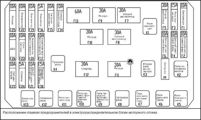
LOCATION OF THE FUSES AND RELAYS IN THE FUSE AND RELAY BOX IN THE ENGINE COMPARTMENT
DESCRIPTION OF THE FUSE AND RELAY BOX IN THE ENGINE COMPARTMENT
| no p p | Description | no p p | Description | no p p | Description |
| EF01 | High beam headlight, right | FY 2017 | ESiDSi (car with CVT) | EF33 | |
| EF02 | Left high beam headlamp | FY 2018 | Replacement | EF34 | Power supply of the ignition system |
| EF03 | Right low beam | FY 2019 | TCU (vehicle with CVT)/ECU | EF35 | Fuel pump |
| EF04 | Left low beam | Fiscal Year 20 | Replacement | EF36 | ABS/ESP system |
| EF05 | Anti-fog headlight | Fiscal Year 21 | — | EF37 | Replacement |
| EF06 | Fiscal Year 22 | — | EF38 | Fuel Pump Relay Coil/Fan Relay Coil | |
| EF07 | Ignition coil | FY 23 | — | EF39 | Oxygen sensor |
| EF08 | Nozzle/camshaft position | FY 24 | — | EF40 | Блок управления |
| EF09 | — | Fiscal Year 25 | Sound signal | EF41 | Home |
| FY 2010 |
| FY 26 | Replacement | EF42 | |
| FY 2011 | FY 27 | Air flow sensor/adsorber | EF43 | IGN1 | |
| FY 2012 | — | FY 28 | Reversing light switch (manual transmission) | EF44 | — |
| FY 2013 | — | Fiscal Year 29 | Generator excitation circuit | EF45 | — |
| FY 2014 | — | EF30 | Reversing Light/Power Reversing Light Sensor (Automotive CVT) | EF46 | TCU (vehicle with CVT) |
| FY 2015 | IGN2 | EF31 | — | EF47 | ABS/ESP system |
| FY 2016 | — | EF32 | EF48 | Power supply scheme for additional electrical equipment |
BLOCK "A" FUSES AND RELAYS INSIDE THE VEHICLE
FUSE AND RELAY LOCATION INSIDE THE VEHICLE FUSE AND RELAY BOX A
DESCRIPTION OF THE INDOOR FUSE AND RELAY BOX
| no p p | Description | no p p | Description | no p p | Description |
| RF01 | Reverse assistance system | RF10 | Air conditioner control panel | RF19 | — |
| RF02 | Illuminated SPORT mode switch | RF11 | RF20 | — | |
| RF03 | Reverse light relay coil (vehicle with CVT) | RF12 | RF21 | Control panel for automatic air conditioning system | |
| RF04 | RF13 | Relay coils for heated rear window, blower, heated seats/audio/BCM | RF22 | Audio system | |
| RF05 | RF14 | Easier | RF23 | Instrument panel/diagnostic connector | |
| RF06 | Yaw Rate Sensor/Steering Angle Sensor/Dashboard/Front Passenger Seat Belt Warning/Diagnostic Connector/Immobilizer/ESP Indicator | RF15 | Mirror Adjustment Switch/Power Sunroof Switch | RF24 | Key sensor |
| RF07 | BCM/EPS/EPS | RF16 | — | RF25 | — |
| RF08 | Air bag | RF17 | — | RF26 | — |
| RF09 | Brake light switch | RF18 | — |
BLOCK "B" FUSES AND RELAYS INSIDE THE VEHICLE
LOCATION OF THE FUSES AND RELAYS IN THE FUSE AND RELAY BOX IN THE INSIDE OF THE VEHICLE
DESCRIPTION OF THE INDOOR FUSE AND RELAY BOX
| no p p | Description | no p p | Description | no p p | Description |
| RF27 | Replacement | RF36 | Replacement | RF45 | Backup power |
| RF28 | — | RF37 | Heated passenger seat | RF46 | power lock |
| RF29 | — | RF38 | RF47 | Engine start/stop button | |
| RF30 | Fuses and relay block A in the cabin | RF39 | RF48 | — | |
| RF31 | — | RF40 | Anti-Pinch Function (Right Door) | RF49 | ventilation hatch |
| RF32 | Electric seat adjustment | RF41 | Anti-pinch function (left door) | RF50 | — |
| RF33 | Rear window defogger | RF42 | Feedback signal for rear defroster and door mirrors | RF51 | — |
| RF34 | Heated driver's seat | RF43 | |||
| RF35 | Brake light switch | RF44 |
Source: http://tiggo-chery.ru/5-t21/8012.html
Wipers do not work on Chery Amulet - the main reasons for how to troubleshoot
The Chery Amulet windshield wiper or the wiper mechanism breaks down very often, which creates certain inconveniences for the driver, and can also lead to an emergency while the car is moving.
There are many reasons for breakdowns, but most of them can be eliminated on their own even by novice drivers. Problems can arise both in the electrical part and in the mechanical drive of the device.
To check the electrics, it is convenient to have a simple car tester or multimeter.
In today's article, I will tell you about the main malfunctions and how to repair the wipers on a Chery Amulet car on your own.
Windshield wipers (windshield wipers) are a special mechanism designed to provide sufficient visibility when driving in bad weather (during rain, hail, snowfall).
If the mechanism fails, the risk of an accident increases, there is a danger to the driver and passengers of the car, as well as to other road users.
What to do if the wipers don't work? What could be the reason? How to solve a problem? These points will be discussed in the article.
Chery Amulet wipers - main malfunctions
There can be quite a few reasons for the failure of the Chery Amulet wipers, but the main one is considered to be a malfunction in the electrical circuit of the wiper or its electromechanical elements. We will not touch the windshield washers, but we will only consider problems with the “wipers”.
Fuse failure glass cleaner Chery Amulet
Like most electrical circuits in a car, the wiper system has a 15 amp F11 fuse. In circuits that change the speed of their work, there is a relay. The number 19 is marked on its cover, and R1 is indicated on the diagram. It can be replaced from a Skoda car, VAZs with five legs are also suitable.
If there is no voltage, you need to find the reason why it is not there. In the windings of the electric motor of the gearbox, it comes from the steering column switch, which sometimes becomes the culprit for its absence.
Replacing the wiper fuse on Chery Amulet
Next, remove fuse F11 and replace it with a new one.
Common malfunctions of Chery Amulet wipers
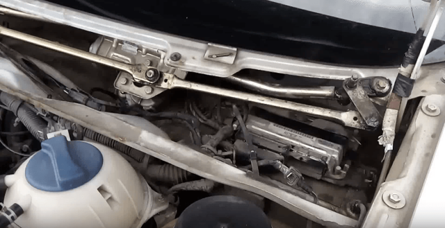
In some cases, when the motor winding terminals are energized, but it does not work, it is too early to cancel the motor.
It is necessary to disassemble the gear motor and check the contacts of the limit switch. It is they who most often burn out during the operation of the windshield washer mechanism.
If checking and cleaning the limit switch contacts did not restore the system to working order, the electric motor should be checked.
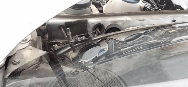
Pay attention to the condition of the brushes and armatures of the device. The brushes in some cases hang down and the anchor can burn out. The stickiness of the brushes is not difficult to remove, the brush must be pulled out of the plinth and filed a little with sandpaper.
Anchor burn is also removed with fine sandpaper. In the event that the burn occurred due to a hanging brush, cleaning will help, but if it burned out due to a break in one of the windings, the damaged armature will have to be replaced.
Fuse and relay boxes [ChinaWiki]
chery:chery_tiggo:fuses
If the cigarette lighter, power windows and rear window defroster are out of order, all at once. We change the F5 fuse (cigarette lighter) in the YB block - it burned out EVERYTHING WORKS. If something has stopped working for you, and this is not in the fuse descriptions, look in the fuse descriptions for what still does not work and change this fuse, by analogy as described above. In relays and fuses, something else can start that is not described in the diagrams.
If you can't find the problem, have questions, suggestions or clarifications, write to the Fuse and Relay Box forum. I made a description. The description of the blocks under the hood and the glove box was originally done by the VGA forum member, for which many thanks to him.
The fuse boxes are located in four places:
- in the engine compartment, on the right in the direction of travel, below a small part of the air intake (on the KK drawings)
- behind a small glove compartment, near the driver's feet (on YB diagrams)
- Behind the large glovebox, at the feet of the passenger Comfort Unit (ISU)
- mains fuses are located on the "+" terminal of the battery
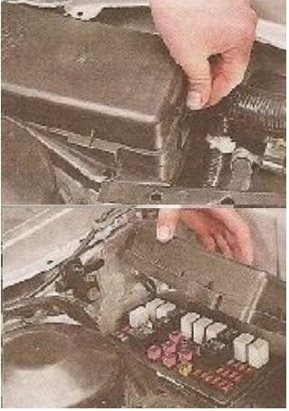
The block can be reached without removing the air intake. We put on gloves, open the hood (do not forget to turn off the ignition key). We bend the right metal latch and open the lid. Next, carefully remove it from under the air intake, it can stick to the wires. Install in reverse order.
Spare fuses are located on the cover, there is also a label with a description of the relay and fuses in English and Chinese.
Figure posted by terra 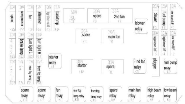
Fuses: 1-low beam (left lamp) 2-low beam (right lamp) 3-fuel pump (relay contacts) 4-high beam (left lamp) 5-cabin fan motor 6-high beam line (right lamp) 7- motor-relay for cooling the engine and air conditioning No. 2 (contacts) 8-motor-relay for cooling the engine and air conditioning No. 3 (contacts) 9-spare 10-11-spare 12-starter (relay contacts) 13-alarm and door lock control device. 14-reverse lamp 15-ignition module 16-generator (excitation coil) 17-right position lights 18-fog lights 19-relay #1, #2)
Relay:
K1 Cabin vent motor relay K2 Fuel pump relay K3 Engine cooling motors relay #3 K4 Starter motor relay K5 Low beam relay K6 High beam relay K7 Cooling motor relay #2 K8 Reserve K9 Front fog lamp relay K10 Rear fog lamp relay K11 Engine coolant relay No. 1 K12 Relay for increasing the speed of the engine cooling motors K13 Reserved
The small glove compartment is removed simply, open it and pull it up slightly, disconnect the spring from the slot in the dashboard.
Spare fuses are located vertically on the left.
- A file with a description of the fuse box in the cabin for a sticker in a small glove compartment.
- Does it look like this:
- Fuses: F1 - instrument lighting dimmer F2 - oxygen concentration sensor, absorber valve, speedometer F3 - fuel injectors F4-A / C F5 - cigarette lighter, power windows, heated mirrors F6 - Dashboard F7 - radio constant power supply F8 - diagnostic connector F9 -Dashboard F10-Rear window wiper F11-Front window wiper F12-Low and high beam relay F13-Airbags F14-Radio (ACC control) F15-Electric mirrors F16-Heated seats F17-Engine ECU F18-ISU alarm and comfort unit F19 -Power windows F20-Sunroof motor F21-Ignition switch (lock) F22-Interior lighting F23-Sunroof control buttons F24-Horn signal F25-Air recirculation door (motor and button) F26-A/C relay F27-Heated rear-view mirrors F28-AM1 ( through the ignition switch goes to the lines ACC and IG1) F29-AM2 (through the ignition switch goes to the line IG2 and to the starter relay coil) F30 - turn on the trunk F30 socket in the trunk F30 socket in the trunk
- Relay:
K1 - Cooling Fan Relay K2, K3, K4 - Spare K5 - Horn Relay K6 - Ignition Relay K7 - A/C Relay
- At the moment there is no clear description.
- This unit is responsible for such functions as: air recirculation, sensors and locks for opening doors and hood, alarm, interior lighting, power windows, direction indicators, emergency lane, open door buzzer, heated mirrors and rear window, and others.
- For details, see: Description of the comfort unit (ISU) and wiring diagram.
Installed near the right foot of the front passenger. To see the fuses, you need to lie on the carpet.
- 30А
- A 20
- 30А
- 15A Central locking
- 25А
- 30А
We remove the red-black casing, unscrew the power cable (most likely it goes to the starter) and remove the second black casing. All cases are fixed with plastic latches. Cables have yellow labels with a number.
Circuit breakers:
- 80A to front compartment of electrical terminal block C
- 60A to front compartment of electrical terminal block B
- ABS power supply 30A
- ABS power supply 30A
- 100 A to supply power to the panel junction box
chery/chery_tiggo/predoxraniteli.txt Last modified: 21.07.2010/00/00 XNUMX:XNUMX (external edit)
Source: http://www.chinamobil.ru/wiki/doku.php/chery:chery_tiggo:predoxraniteli
Chery tiggo fl fuses
Assessment of the owner of the car named Andrey: 1. The interior is spacious, there is enough space for passengers in the back.2. Salon cloth of worthy properties3. Appearance and party and peace and good people are not ashamed.4. The patency is good, the clearance is small because of the protection. Believe me, it is no worse than an x-trail, and it’s better not to cling to the trunk, like an x-trail, through huge pits.
Jeepers on the lakeshore once saw me crawling on my belly through a puddle with a groove from their fields and patriots. I didn't know it was that deep, but they dropped their fishing rods and looked at me when I rode up to him, and not a single person told you not to go deep there. Drove only tsepanul belly but crawling on standard tires.
Well, in the fall, I twisted the cork on the lawn in the fall on my belly in peat, crawled 200 m, I thought I wouldn’t pass (1 experience on that) or puddles, because the engine stalls by almost 0,5.
The stability of the course and the anti-skid system for 5+ really helped out a couple of times, and 1 time on ice with snowfall.6. Large trunk, a little shorter x trail.7. Excellent light and tumanki.8. The paint is of very good quality, let's see how the dealer's OF will paint the mirror and 2 doors (the car is scratched in the parking lot).9.
Suspension is well balanced both on asphalt and off-road
- Written by admin: at the request of Henry
- Category: DIY car
- Original name:
Description: The dimensions are as follows, length - 3079, width - 1100, height - 1205 mm. The wheelbase is 2991 mm. Ground clearance 111 mm. The car is equipped with a hybrid drive system.
The 2-cylinder engine is equipped with a system that provides engine power output. There are 4 valves per cylinder with a diameter of one
cylinder 70 mm, piston stroke 75 mm. The crankshaft of the engine accelerates to 4000 rpm.
The maximum torque is maintained up to 5000 rpm.
Views: 2991
Below you can find the technical specifications of Cherry Tiggo Fl. Express your opinion about the car in the comments.
Release date: 16.07.2019
Duration: 1: 07
Quality: PDTV
Laughs on the topic: Two brothers 5 and 7 years old. The senior reads the name of the notebook in syllables: - Pro-pi-si Interested Junior: - About what?
Where are the fuses on the Chery Tiggo
The Chery Tiggo is a compact crossover SUV from China's Chery Automobile Co., Ltd that competes with the Renault Duster, Toyota RAV4 and Hyundai Tucson in terms of quality and performance. One of the main systems that ensure their movement (in particular, the operation of electrical appliances) are fuses and relays.
This model has two blocks of devices that control the movement of current and its strength. One of them is under the hood (in the engine compartment), and the other is in the cabin (under the dashboard, on the left side).
Features of Chery Tiggo engine compartment fuses, their replacement
The exact location of the fuse and relay box is at the rear of the engine compartment, closer to the windshield end plate. If you move in the direction of the car, then it is on the right side.
This block contains Chery Tiggo fuses responsible for the operation of the right and left headlights (low / high beam), lights (rear, small and large front, as well as fog lights), brake light, generator, compressor, fan and some other devices working with the use of electricity. Also in the engine compartment are various non-original components of different capacities.
You can replace fuse links in just 4 easy steps.
- Disconnect the vehicle from the mains (switch off all electrical systems).
- Disconnect the battery from the junction box.
- We unscrew the clips from the plastic casing, which are located on the block.
- Remove the cover and replace the blown fuse link.
The location of the fuses is indicated on the inside of the cover in the same way as in the diagram in the instructions for the car. Spare fuse links and alligator clips for installation can also be found on the lid.
Cabin fuses and their replacement
You can find the fuses installed in the Chery Tiggo cabin if you open a small glove compartment. This block is located vertically, "facing" to the driver. It contains fuses that are responsible for the internal electrical systems of the car: air conditioning, airbags, audio system, interior lighting, heating, dashboard and windshield wipers.
Replacing the fuses in this box is easier as it is easier to find and open. You can remove burnt parts and install new ones without getting up from the driver's seat. The procedure is carried out with special tweezers inserted into one of the sockets of the block.