Fuses and relays Lexus px 300, Toyota Harrier
The first generation Toyota Harrier right-hand drive crossover was produced in 1997, 1998, 1999, 2000, 2001, 2002 and 2003. During this time, the model was restyled. In some countries of the world it is known as the Lexus RX 300. These cars differ in the location of the steering wheel. In the Lexus px 300, he is on the other side. Their schemes are similar. In this article, we will show the location of the electronic control units, the description of the fuses and relays on the Lexus px 300 (Toyota Harrier UA10) with block diagrams and where they are located. Select the cigarette lighter fuse.
Blocks in the salon
The general arrangement of blocks in the cabin
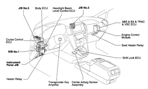
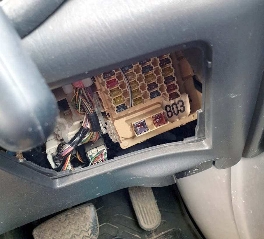
Fuse box
It is located at the bottom of the instrument panel behind a protective cover on the driver's side.
scheme
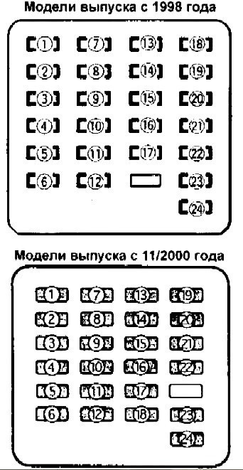
Description
| one | 7.5A IGN - Electronic engine control unit |
| two | 7.5A RADIO #2 - Audio System |
| 3 | 15A CIG - cigarette lighter, power side mirrors |
| 4 | 20A PRR DOOR - rear left door with electric window |
| 5 | 15A PWR OUTLET - Socket for connecting additional equipment |
| 6 | 15A FR FOG - Front fog lights |
| 7 | 15A SRS - Airbag System (SRS) |
| eight | 15A ECU-IG - ABS, TRC systems |
| nine | 25A WIPER - wiper arm and brush |
| ten | 20A D RR DOOR - Right rear door power window |
| 11 | 20A D FR DOOR - Driver's door with power windows, central locking |
| 12 | 20A S/ROOF - Hatch |
| thirteen | 15A HEATER - Air conditioning and heating, rear window defroster |
| 14 | COUNTER 7,5A - Dashboard |
| fifteen | 15A RR WIP - Rear door wiper blade and arm |
| sixteen | 20A STOP - Brake lights |
| 17 | 7.5A OBD - Electronic engine control unit |
| Eighteen | STARTER 7,5A - Starter |
| (Eighteen)* | 15A HTR SEAT - Heated seats |
| nineteen | 10A WASHER - windshield washer |
| (nineteen)* | STARTER 7,5A - Starter |
| twenty | 7.5A RR FOG - Rear fog lights |
| (twenty)* | 10A WASHER - windshield washer |
| 21 | 20A FR DEF - Wiper defroster |
| (21) * | 7.5A RR FOG - Rear fog lights |
| 22 | 7.5A SRS-B - Airbag System (SRS) |
| (22) * | 20A FR DEF - Wiper defroster |
| 23 | 10A TAIL - Dimensions front and rear, license plate light |
| 24 | PANEL 7.5A - Light switches and switches |
* - Models from 11/2000 of release.
Fuses 3 and 5 at 15A are responsible for the cigarette lighter.
Fuses are mounted separately at the bottom: 40A AM1 - Ignition, 30A POWER - Seat drive.
Relay elements are located on the reverse side of the block.
scheme
Goal
- A - Side light relay
- B - Fog lamp relay
- C - Power Relay ("ACC")
- D - Brush heater relay
- E - Rear fog lamp relay
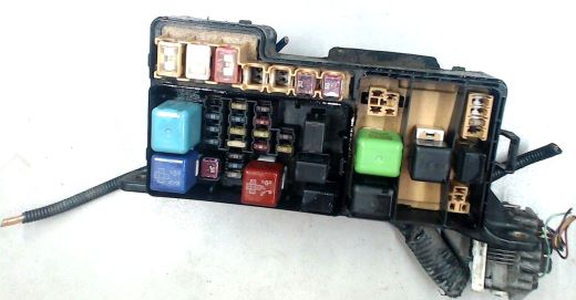
Blocks under the hood
Fuse and relay box
Located on the left side of the engine compartment, next to the battery.
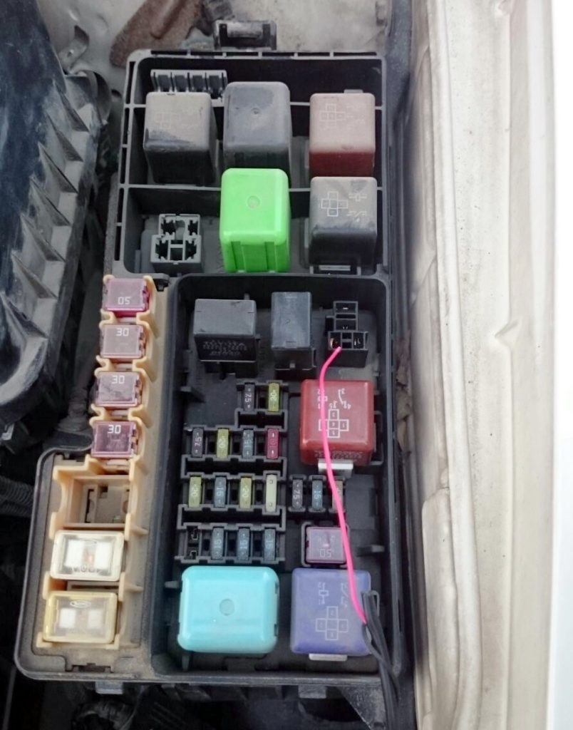
Check the purpose of the elements with their diagrams on the block cover.
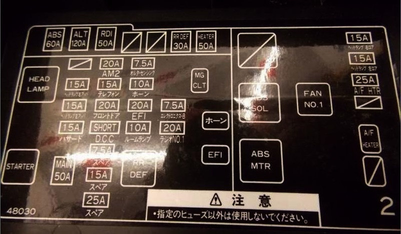
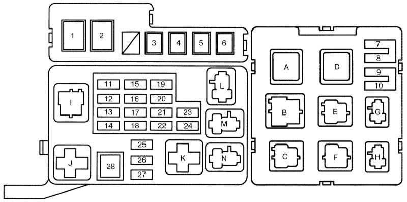
scheme
Fuse designation
| one | ABS 60A - ABS |
| two | 140A ALT - charging system |
| 3 | RDI 40A FAN - Cooling fan |
| 4 | 40A CDS FAN - Cooling fan |
| 5 | 30A RR DEF - Heated rear door glass and exterior mirrors |
| 6 | HEATER 50A — Heater fan |
| 7 | 15A H - LP R UPR - Right headlight, high beam |
| eight | 15A H - LP L UPR - left headlight, high beam |
| nine | 25A A/F HTR - Mixture Quality Sensor |
| 10 11 | - |
| 12 | 15A H - LP R LWR - Right headlight, low beam |
| thirteen | 15A H - LP L LWR - Left headlight, low beam |
| 14 | 15A DANGER - danger sign, direction indicators |
| fifteen | 20A AM 2 - Starting system |
| sixteen | 20A PHONE |
| 17 | DOOR 20A FL |
| Eighteen | - |
| nineteen | 7.5A ALT - S - Charging system |
| twenty | 10A HORN - Anti-theft system, horn |
| 21 | 20A EFI - fuel injection |
| 22 | 10A DOMO - Interior lighting, indicators and gauges, multifunction display |
| 23 | 7.5A ECU - B - On-board computer |
| 24 | 20A RAD #1 — Audio System |
| 25 26 27 | - |
| 28 | 50A BASIC - Starting System |
Relay decoding
- No one
- B - ABS SOL relay
- C - Fan Relay #3
- D - Fan Relay #1
- E - ABS motor relay
- F - Fan relay #2
- G - A/C sensor relay
- N- no
- I - Headlight relay
- J - Start relay
- K - Relay for heating the glass of the rear door and outside rear-view mirrors
- L - Air conditioner magnetic clutch relay
- M - Horn and anti-theft relay
- N - Fuel injection relay
Relay box 1
scheme
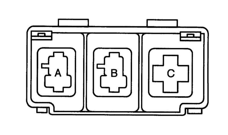
Description
- A - Open relay circuit
- B - Main engine relay
- C - Heated exterior mirror relay
Relay box 2
scheme
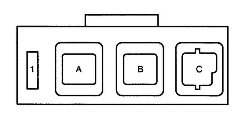
- 1 - fuse daytime running lights (DRL) 7,5 A
- A - Relay No. 2 DRL
- B - Relay No. 4 DRL
- C - Relay No. 3 DRL