Fuses and relay Toyota Carina E T190
Toyota Carina E is the sixth generation of the Carina line, which was produced in 1992, 1993, 1994, 1995, 1996, 1997 and 1998 with hatchback (liftback), sedan and wagon bodies. During this time it has undergone a redesign.
This model is the European version of the left-hand drive Toyota Crown T190 of the ninth generation. These machines are very similar, the key difference being the location of the address. In this publication you can find a description of the fuses and relays Toyota Carina E (Crown T190) with block diagrams and their location. Pay attention to the fuse responsible for the cigarette lighter.

The execution of the blocks and the purpose of the elements in them may vary and depend on the region of delivery (Karina E or Corono T190), the level of electrical equipment, the type of engine and the year of manufacture.
Block in the cabin
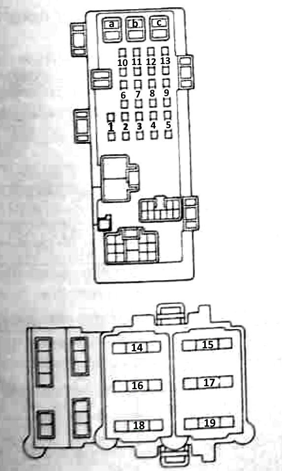
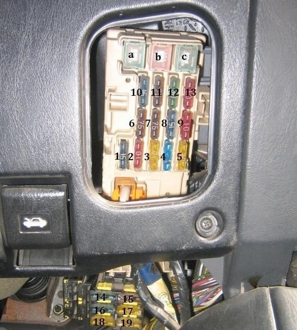
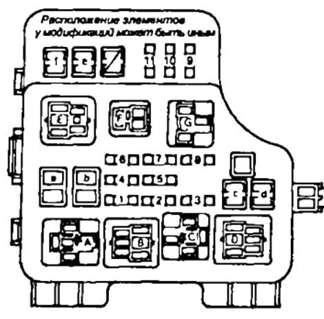
In the passenger compartment, the main fuse box is located in the instrument panel behind a protective cover.
Photo - scheme
Description
| к | 40A AM1 (output of the ignition switch circuit AM1 (outputs ACC. IG1. ST1) |
| б | 30A POWER (power windows, sunroof and central locking) |
| with | 40A DEF (Heated rear window) |
| а | 15A STOP (stop lights) |
| two | TAIL 10A (dimensions) |
| 3 | 20A MAIN REAR (dimensions) |
| 4 | 15A ECU-IG (transmission electronics. ABS, lock control system (automatic transmission) |
| 5 | 20A WINDSHIELD WIPER (Wiper) |
| 6 | 7.5A ST (starting system) |
| 7 | 7,5 A IGN (ignition) |
| 8 | 15A CIG & RAD (cigarette lighter, radio, clock, antenna) |
| 9 | 10A TURN |
| 10 | 15A ECU-B (ABS, central locking power) |
| 11 | PANEL 7.5A (instrument lighting, glove box lighting) |
| 12 | 30A FR DEF (Heated rear window) |
| thirteen | CALIBER 10A (instruments) |
| 14 | 20A SEAT HTR (seat heating) |
| fifteen | 10A WORLD HTR (heated mirror) |
| sixteen | 20A FUEL HTR (fuel heater) |
| 17 | 15A FR DEF IAJP (Idle speed increases with defroster on) |
| 18 | 7,5A RR DEF 1/UP (Increases idle speed when rear window defroster is on) |
| night | 15A FR FOG (fog lights) |
For the cigarette lighter, fuse No. 8 at 15A is responsible.
Blocks under the hood
In the engine compartment, various blocks with fuses and relays can be located.
General arrangement of blocks
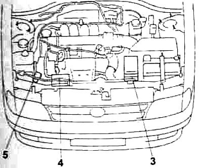
designation
- 3 - the main block of relays and fuses
- 4 - relay block
- 5 - additional block of relays and fuses
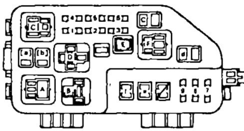
Main unit
There are several options for its implementation.
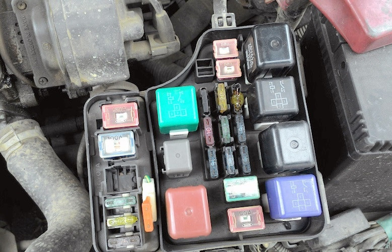
Option 1
scheme
Goal
| Circuit breakers | |
| к | 50A HTR (Heater) |
| б | 40A MAIN (main fuse) |
| with | 30A CDS (condenser fan) |
| г | 30A RDI (air conditioner radiator fan) |
| me | 100A alternative (charging) |
| ф | ABS 50A (ABS) |
| а | 15A HEAD RH* (right headlight) |
| two | 15A HEAD LH* (left headlight) |
| 3 | 15A EFI (injection system) |
| 4 | replacement |
| 5 | replacement |
| 6 | 15A DANGER (alarm) |
| 7 | 10A HORN (horn) |
| 8 | — |
| 9 | ALTERNATIVE SENSOR 7,5A (Load) |
| 10 | DOMO 20A (electric drive and interior lighting) |
| 11 | 30A AM2 (AM3 ignition switch circuit, IG2 ST2 terminals) |
| Relay | |
| К | STARTER — Starter |
| В | HEATER - Heater |
| WITH | MAIN EFI - injection system |
| Д | MAIN MOTOR - Main Relay |
| Me | HEAD - Headlights |
| Ф | HORN — Signal |
| GRAM | FAN #1 - Radiator fan |
Option 2
Photo - example
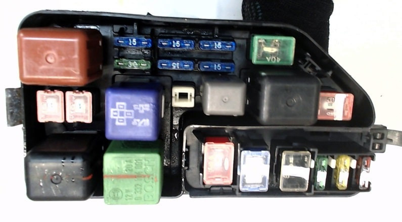
scheme
transcribed
| к | CDS (condenser fan) |
| б | RDI (air conditioner radiator fan) |
| с | MAIN (main fusible link) |
| г | HTR (heater) |
| me | 100A alternative (charging) |
| ф | ABS 50A (ABS) |
| а | |
| two | HEAD LH (left headlight) |
| 3 | ROG (horn) |
| 4 | |
| 5 | HEAD RH* (right headlight) |
| 6 | DANGER (alarm) |
| 7 | ALTERNATIVE SENSOR 7,5A (Load) |
| 8 | DOMO 20A (electric drive and interior lighting) |
| 9 | 30A AM2 (AM3 ignition switch circuit, IG2 ST2 terminals) |
| Relay | |
| К | MAIN MOTOR - Main Relay |
| В | FAN #1 - Radiator fan |
| С | HEAD - Headlights |
| Д | STARTER — Starter |
| Me | ROG — Horn |
| Ф | HEATER - Heater |
Relay box
scheme
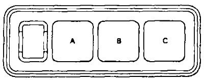
Description
- A - A/C FAN #2 - Radiator fan relay
- B - FAN A/CN° 3 - Radiator fan relay
- C - A/C MG CLT - A/C Clutch