Gearbox drive Maz 5440 zf
Content
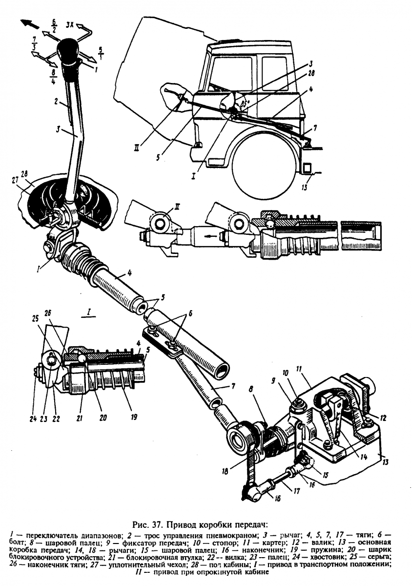
The gearbox of MAZ-64227, MAZ-53322 cars during operation provides the following settings:
- the position of the lever 3 (Fig. 37) shifting gears in the longitudinal direction;
- the position of the gear lever in the transverse direction;
- locking device for longitudinal traction of telescopic elements.
To adjust the angle of inclination of the lever 3 in the longitudinal direction, it is necessary to loosen the nuts of the screws 6 and, moving the rod 4 in the axial direction, adjust the angle of inclination of the lever to approximately 85° (see Fig. 37) in the neutral position of the gearbox.
The adjustment of the position of the lever in the transverse direction is carried out by changing the length of the transverse link 77, for which it is necessary to disconnect one of the tips 16 and, having unscrewed the nuts, adjust the length of the link so that the gearbox control lever, being in the neutral position against rotation on the 6-2nd and 5 -1st gear, had an angle of approximately 90 ° with the horizontal plane of the cab (in the transverse plane of the car).
Adjustment of the gearshift locking device should be made as follows:
- raise the cab
- release pin 23 and disconnect stem 4 from fork 22;
- clean the earring 25 and the inner rod from old grease and dirt;
- press on the inner rod 5 until the stop sleeve 21 clicks;
- unlock the earring nut 25;
- inserting a screwdriver into the groove of the rod 24 of the internal thrust, unscrew it until the angular play of the earring disappears;
- without turning the stem 24, tighten the locknut;
- check the quality of the fit.
When the lock sleeve 27 moves towards the spring 19, the inner rod must extend without sticking to its full length, and when the rod is pressed all the way into the grooves, the lock sleeve must move clearly with a “click” until the sleeve rests against the lower protrusion of the earring.
When adjusting the drive, the following requirements must be taken into account:
- adjustment must be made with the cab raised and the engine turned off;
- avoid bends and kinks of external and internal movable rods;
- to avoid breakage, connect stem 4 with fork 22 so that the hole in the earring for pin 23 is above the longitudinal axis of stem 4;
- check the neutral position of the gearbox with the cab raised by free movement of the lever 18 of the gearbox
- gears in the transverse direction (with respect to the longitudinal axis of the vehicle). The roller 12 in the neutral position of the box has an axial movement equal to 30-35 mm; feel the compression of the spring.
MAZ gearbox drive - how to adjust?
When working with the MAZ 5335 gearbox, the gear is adjusted to improve the fixation of the paired gearbox. The workflow includes several steps. In this article, we will talk in detail about how to quickly adjust the MAZ 5335 gearbox.
We advise you to repair MAZ only in accordance with the manufacturer's recommendations.
Also, if you are not confident in your own abilities, entrust the drive and its adjustment to professionals.
Check fork travel every time you service your vehicle. To do this, we advise you to take the lever.
We mount it in a neutral place.
Engage first gear only after measuring the distance between the surface of the flywheel housing and the fork. Do the same for reverse.
If you see that the stroke does not exceed twelve mm, you need to adjust the MAZ gearbox as follows:
- Move the lever to the "neutral" position;
- Carefully remove the number five tip from the earring and also from the invisible hairpin. Note that the lever is only in the neutral position and the fork is in the vertical position;
- Stop roller number thirteen. To do this, it is necessary to wrap the element into the corresponding hole until it stops. It's on a roller;
- Loosen all bolts as much as possible. With the help of the tip, the thrust on the top ten is regulated. Please note: finger six must be placed in the hole of the fork at number eight, the earring of the fork. The two holes must be aligned.
- We connect the earring and the tip;
- When adjusting the MAZ gearbox, it is necessary to tighten all the coupling elements;
- Bolt #12 goes 8 turns. At the end, fix it with a nut;
Scenery on MAZ
The link of the gearbox is called the multi-link mechanism of the assembly, which connects the gear lever and the rod supplied to the box. The location of the scenes, as a rule, is made under the bottom of the car, in the same place as the suspension. This arrangement facilitates the possibility of dirt getting inside the mechanism, which will cause deterioration of the properties of lubricating oils and, as a result, wear of the mechanism.
The purpose of the checkpoint
In the gearbox there is such an element as a gear, usually there are several of them, they are connected to the gear lever and it is due to them that the gear changes. Gear shifting controls the speed of the car.
So, in other words, gears are gears. They have different sizes and different rotation speeds. In the course of work, one clings to the other. The system of such work is due to the fact that a large gear sticks to a smaller one, increases the rotation, and at the same time the speed of the MAZ vehicle. In cases where a small gear sticks to a large one, the speed, on the contrary, drops. The box has 4 speeds plus reverse. The first is considered the lowest and with the addition of each gear, the car starts to move faster.
The box is located on the MAZ car between the crankshaft and the cardan shaft. The first comes directly from the engine. The second is directly connected to the wheels and drives their work. List of works leading to speed control:
- The engine drives the transmission and crankshaft.
- The gears in the gearbox receive a signal and start moving.
- Using the gear lever, the driver selects the desired speed.
- The speed selected by the driver is transmitted to the propeller shaft, which drives the wheels.
- The car continues to move at the selected speed.
Backstage adjustment MAZ
Therefore, it is important to regularly check and adjust the transmission link. Initially, it is necessary to evenly adjust and fix the base of the lever, this allows you to get rid of the gearshift lubrication that occurs over time during the operation of the car.
This rod contains two special tips that regulate the movement of the lever in the horizontal direction, that is, if the lever encounters an "obstacle" when performing a turn action in the extreme rows, then it is necessary to lengthen the rod. If the link of the gearbox encounters an “obstacle” at the moment of shifting forward, then it is necessary to fully lengthen the entire “gun”. And due to the “stopping” of the wings in the movement of a vertical strike, i.e. back and forth, it is required to reduce the length of the weapon.
When the handle of the on-off system of the gearbox staggers left and right and there is no point in fixing it, then at the top of the backstage body you need to loosen the lock nut, and slightly unscrew the screw with a screwdriver, which will set the moment of the gear selection rod in the neutral position. After that, it is necessary to check the ability of the lever to move back and forth until the spring stops completely, then it is necessary to unscrew the screw until the stem begins to move strongly and click.
See also: What is the difference between mono-wheel drive and front-wheel drive
Backstage adjustment KAMAZ 4308 KAMAZ
KAMAZ speed does not include
Gearbox ZF for KAMAZ 6520. Location and gear shifting.
KAMAZ clutch basket adjustment
Gearbox in a KAMAZ car (switching scheme) for subscribers
KAMAZ vehicles with Cummins Cummins ISLe340/375 engines
Valve adjustment KAMAZ - New Method
Review Kamaz 65115 Restyling
Here's how to change gears in a car
- How to check the starter anchor KAMAZ
- I need a KAMAZ with a trailer
- Video of experienced KAMAZ trucks
- What does KAMAZ look like without a trailer
- Plastic lubricants KAMAZ
- Collar of fastening of the KAMAZ fuel tank
- What the plant fills on KAMAZ bridges
- Weight of gearbox KAMAZ 4310
- How to remove the window lifter handle on KAMAZ euro
- KAMAZ engine for EU 2
- 2008 KAMAZ Stopped
- How to open the door on KamAZ without a key
- Why did the KAMAZ piston burn out
- Repair kits for KAMAZ shock absorbers
- How to bleed air on a KAMAZ trailer
Gearbox control drive YaMZ cars Maz-5516, Maz-5440
The gearbox of Maz-5516, Maz-5440, 64229, Maz-54323, 54329 and YaMZ-239 cars is shown in Figure 4. During operation, if necessary, the following gearbox adjustments are made:
- adjustment of the position of the lever in the longitudinal direction;
— adjustment of the position of the lever in the transverse direction;
- adjustment of the locking device of the telescopic drive elements.
The procedure for adjusting the control of the YaMZ-239 gearbox for Maz-5516, Maz-5440, 64229, Maz-54323, 54329 cars is as follows:
- put lever 2 in neutral position;
— adjust the angle a of the lever 16 by moving the plate 17 with the bolts 1 released;
— change the length of the rod 3 to adjust the angle.
If the stroke of the plate 16 or the adjustment range of the rod 3 is insufficient, loosen the bolts 5, shift or turn the rod 6 relative to the rod 4, tighten the bolts 5 and repeat the adjustment of the angle a, b, as indicated above.
Angle a must be 80°, angle b 90°.
The adjustment of the locking device for the telescopic elements of the YaMZ-239 gearbox for Maz-5516, Maz-5440, 64229, Maz-54323, 54329 vehicles with a raised cab is performed as follows:
- release the pin 8 and disconnect the rod 6 from the fork 9 of the gear lever;
- loosen the lock nut 13 and unscrew the stem 14 until the thread stops;
- slide the inner rod 6 to the stop of the protrusions of the earring 12 into the grooves of the tip 15;
- while holding the mechanism in a compressed state, screw the rod until the mechanism is blocked by the sleeve K) under the action of spring 11:
- tighten the locknut 13, check the clarity of the locking mechanism. When the mechanism is locked, the axial and angular play must be minimal.
In the unlocked position, the sleeve 10 moves to the left. The movement of the extension must be smooth, without jamming, and the locking mechanism must provide a clear fixation of the rod extension in its original position.
When link 6 is connected to fork 9, the hole in the earring for pin 8 must be located above the longitudinal axis of link 6. Adjust the gear with the engine off.
When lifting the cabin, oil under pressure from the cabin lifting pump is supplied through hose 7 to the lock cylinder and mechanism 6 is unlocked.
After lowering the cab, in order to securely fix the telescopic mechanism 6 in the lock position, it is necessary to move the gearshift lever 1 forward in the direction of the vehicle in a movement similar to gear shifting. In this case, the mechanism is blocked, after which it is ready for operation.
The gearshift diagram of the gearbox of the Maz-5516, Maz-5440, 64229, Maz-54323, 54329 and YaMZ-239 cars is shown in Figure 5.
Figure 4. YaMZ gearbox control unit for Maz-5516, 64229, Maz-54323, 54329 cars
1 - lever; 2 - lever; 3,4 - thrust; 5.17 - bolt; 6 - thrust (telescopic mechanism); 7 - hose; 8 - finger; 9 - fork; 10 - sleeve; 11 - spring; 12 - slope; 13 - locknut; 14 - trunk; 15 - tip; 16 - plate; 18 - switch
Transmission control unit for Maz-5516, Maz-5440, 64229, Maz-54323, 54329 vehicles with MAN engine
The gearbox of MAZ-64227, MAZ-53322 cars during operation provides the following settings:
- the position of the lever 3 (Fig. 37) shifting gears in the longitudinal direction;
- the position of the gear lever in the transverse direction;
- locking device for longitudinal traction of telescopic elements.

To adjust the angle of inclination of the lever 3 in the longitudinal direction, it is necessary to loosen the nuts of the screws 6 and, moving the rod 4 in the axial direction, adjust the angle of inclination of the lever to approximately 85° (see Fig. 37) in the neutral position of the gearbox.
The adjustment of the position of the lever in the transverse direction is carried out by changing the length of the transverse link 77, for which it is necessary to disconnect one of the tips 16 and, having unscrewed the nuts, adjust the length of the link so that the gearbox control lever, being in the neutral position against rotation on the 6-2nd and 5 -1st gear, had an angle of approximately 90 ° with the horizontal plane of the cab (in the transverse plane of the car).
Adjustment of the gearshift locking device should be made as follows:
- raise the cab
- release pin 23 and disconnect stem 4 from fork 22;
- clean the earring 25 and the inner rod from old grease and dirt;
- press on the inner rod 5 until the stop sleeve 21 clicks;
- unlock the earring nut 25;
- inserting a screwdriver into the groove of the rod 24 of the internal thrust, unscrew it until the angular play of the earring disappears;
- without turning the stem 24, tighten the locknut;
- check the quality of the fit.
When the lock sleeve 27 moves towards the spring 19, the inner rod must extend without sticking to its full length, and when the rod is pressed all the way into the grooves, the lock sleeve must move clearly with a “click” until the sleeve rests against the lower protrusion of the earring.
When adjusting the drive, the following requirements must be taken into account:
- adjustment must be made with the cab raised and the engine turned off;
- avoid bends and kinks of external and internal movable rods;
- to avoid breakage, connect stem 4 with fork 22 so that the hole in the earring for pin 23 is above the longitudinal axis of stem 4;
- check the neutral position of the gearbox with the cab raised by free movement of the lever 18 of the gearbox
- gears in the transverse direction (with respect to the longitudinal axis of the vehicle). The roller 12 in the neutral position of the box has an axial movement equal to 30-35 mm; feel the compression of the spring.
Backstage adjustment on MAZ
Scenery on MAZ
The link of the gearbox is called the multi-link mechanism of the assembly, which connects the gear lever and the rod supplied to the box. The location of the scenes, as a rule, is made under the bottom of the car, in the same place as the suspension. This arrangement facilitates the possibility of dirt getting inside the mechanism, which will cause deterioration of the properties of lubricating oils and, as a result, wear of the mechanism.
Backstage adjustment MAZ
Therefore, it is important to regularly check and adjust the transmission link. Initially, it is necessary to evenly adjust and fix the base of the lever, this allows you to get rid of the gearshift lubrication that occurs over time during the operation of the car.
This rod contains two special tips that regulate the movement of the lever in the horizontal direction, that is, if the lever encounters an "obstacle" when performing a turn action in the extreme rows, then it is necessary to lengthen the rod. If the link of the gearbox encounters an “obstacle” at the moment of shifting forward, then it is necessary to fully lengthen the entire “gun”. And due to the “stopping” of the wings in the movement of a vertical strike, i.e. back and forth, it is required to reduce the length of the weapon.
When the handle of the on-off system of the gearbox staggers left and right and there is no point in fixing it, then at the top of the backstage body you need to loosen the lock nut, and slightly unscrew the screw with a screwdriver, which will set the moment of the gear selection rod in the neutral position. After that, it is necessary to check the ability of the lever to move back and forth until the spring stops completely, then it is necessary to unscrew the screw until the stem begins to move strongly and click.
After some time, when working with a lever, there is a chance to find a "telescope" hole. This problem appears with frequent use of the vehicle in large cities, where there are usually traffic jams. To remove it, it is necessary to loosen the nut at the end of the “telescope” lock and unscrew the fastening of the lever fork by a certain number of turns. This will allow you to fix the gear lever in a more “solid” state and increase the clarity of gear shifting.
Summing up, it should be noted that the setting behind the scenes comes after the appearance of some minor problems. Such as weakening of traction, deterioration in the clarity of gear shifting, possible "loss of hole" for gear shifting, etc. A working link, of course, does not require adjustment, but keeping it in “perfect condition” is the responsibility of every driver, since the quality of the link directly affects the quality of gear shifting.
How to adjust the slide on the ointment
The gearbox of Maz-5516, Maz-5440, 64229, Maz-54323, 54329 and YaMZ-239 cars is shown in Figure 4. During operation, if necessary, the following gearbox adjustments are made:
- adjustment of the position of the lever in the longitudinal direction;
— adjustment of the position of the lever in the transverse direction;
- adjustment of the locking device of the telescopic drive elements.
The procedure for adjusting the control of the YaMZ-239 gearbox for Maz-5516, Maz-5440, 64229, Maz-54323, 54329 cars is as follows:
- put lever 2 in neutral position;
— adjust the angle a of the lever 16 by moving the plate 17 with the bolts 1 released;
— change the length of the rod 3 to adjust the angle.
If the stroke of the plate 16 or the adjustment range of the rod 3 is insufficient, loosen the bolts 5, shift or turn the rod 6 relative to the rod 4, tighten the bolts 5 and repeat the adjustment of the angle a, b, as indicated above.
Angle a must be 80°, angle b 90°.
The adjustment of the locking device for the telescopic elements of the YaMZ-239 gearbox for Maz-5516, Maz-5440, 64229, Maz-54323, 54329 vehicles with a raised cab is performed as follows:
- release the pin 8 and disconnect the rod 6 from the fork 9 of the gear lever;
- loosen the lock nut 13 and unscrew the stem 14 until the thread stops;
- slide the inner rod 6 to the stop of the protrusions of the earring 12 into the grooves of the tip 15;
- while holding the mechanism in a compressed state, screw the rod until the mechanism is blocked by the sleeve K) under the action of spring 11:
- tighten the locknut 13, check the clarity of the locking mechanism. When the mechanism is locked, the axial and angular play must be minimal.
In the unlocked position, the sleeve 10 moves to the left. The movement of the extension must be smooth, without jamming, and the locking mechanism must provide a clear fixation of the rod extension in its original position.
When link 6 is connected to fork 9, the hole in the earring for pin 8 must be located above the longitudinal axis of link 6. Adjust the gear with the engine off.
When lifting the cabin, oil under pressure from the cabin lifting pump is supplied through hose 7 to the lock cylinder and mechanism 6 is unlocked.
After lowering the cab, in order to securely fix the telescopic mechanism 6 in the lock position, it is necessary to move the gearshift lever 1 forward in the direction of the vehicle in a movement similar to gear shifting. In this case, the mechanism is blocked, after which it is ready for operation.
The gearshift diagram of the gearbox of the Maz-5516, Maz-5440, 64229, Maz-54323, 54329 and YaMZ-239 cars is shown in Figure 5.
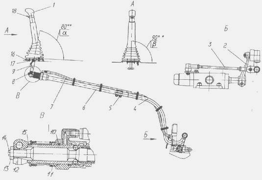
Figure 4. YaMZ gearbox control unit for Maz-5516, 64229, Maz-54323, 54329 cars
1 - lever; 2 - lever; 3,4 - thrust; 5.17 - bolt; 6 - thrust (telescopic mechanism); 7 - hose; 8 - finger; 9 - fork; 10 - sleeve; 11 - spring; 12 - slope; 13 - locknut; 14 - trunk; 15 - tip; 16 - plate; 18 - switch
Transmission control unit for Maz-5516, Maz-5440, 64229, Maz-54323, 54329 vehicles with MAN engine
When working with the gearbox of Maz-5516, Maz-5440, 64229, Maz-54323, 54329 cars, be guided by the following:
— The main gearbox and the gearbox are controlled by the gearbox lever according to the scheme shown in Figure 19 (ZF gearbox).
- The transition from the slow to the fast range of the gearbox is made by moving the lever in the neutral position away from you, overcoming the clamping force, from the fast to the slow range - in the reverse order.
- The divider is controlled by a flag on the gear lever handle. The transition from the slow range (L) to the fast range (S) and vice versa is carried out by fully depressing the clutch pedal after moving the flag to the appropriate position. Shifting is possible without disengaging the gear in the main gearbox.
Adjustment of the gearbox control drive of cars Maz-5516, Maz-5440, 64229, Maz-54323, 54329
During operation, if necessary, the following adjustments are made to the gearbox of Maz-5516, Maz-5440, 64229, Maz-54323, 54329 cars for MAN engines:
- adjustment of the position of the lever in the longitudinal direction;
— adjustment of the position of the lever in the transverse direction;
- adjustment of the locking device of the telescopic drive elements.
The position of the lever 1 (Fig. 7) in the longitudinal and transverse directions is regulated by moving and turning the rod 5 on the rod 6 with the bolts 7 released.
In this case, the angle a must be equal to 85°, the angle e=90°. The angle and can also be adjusted by moving the plate 3 with the bolts 2 released.
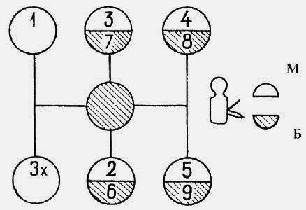
Figure 5. Gearshift diagram of the gearbox of cars Maz-5516, Maz-5440, 64229, Maz-54323, 54329, YaMZ-239
Read also: Drive dvd rw apple usb superdrive zml macbook md564zm a
M - slow range; B - fast range.
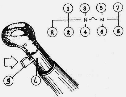
Figure 6. Gearshift diagram of the ZF gearbox for Maz-5516, Maz-5440, 64229, Maz-54323, 54329
L - slow range; S is the fast range.
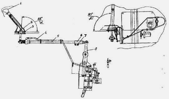
Figure 7. The control unit for the gearbox of cars Maz-5516, Maz-64229, Maz-54323, 54329
1 - lever; 2, 7 - bolt; 3 - plate; 4 - hose; 5 - intermediate mechanism; 6 - trunk; 8 - growl
The gearbox of Maz-5440 cars is shown in Figure 8.
The change of the main box is carried out by lever 1 of the remote control mechanism. The additional box is controlled by the range switch 18 located on the gear lever 1.
When the range selector is in the down position, the secondary field will switch to the fast range, and in the up position, the slow range will be enabled.
During operation, if necessary, the following adjustments are made to the gearbox of Maz-5440 cars:
- adjustment of the angle of inclination of the lever 1 in the longitudinal direction;
- adjustment of the angle of inclination of the lever 1 in the transverse direction;
- adjustment of the locking device of the telescopic mechanism. To adjust the angle of inclination of the lever in the longitudinal direction, it is necessary:
- put the lever 2 in the neutral position by tightening the neutral position lock on the shift mechanism 20 (for the YaMZ-238M gearbox).
Check the neutral position of the MAZ-5440 gearbox by moving the lever axis 2 in the axial direction by pressing it with your hand. In this case, the roller should move 30–35 mm;
- loosen the screws 17 and, moving the plate 16, adjust the angle "a" in the longitudinal direction to 90 degrees;
— if the stroke of plate 16 is insufficient, loosen screws 5, move stem 6 relative to stem 4, tighten screws 5 and repeat the adjustment of angle “a” by moving plate 16.
The adjustment of the lever 1 in the transverse direction is carried out by changing the length of the transverse link 3 by detaching one of the tips with unscrewing the nut from its fastening, then adjusting the length so that the lever 1 assumes a vertical position.
After adjustment, return the neutral position lock to its original position (for the YaMZ-238M gearbox).
Adjustment of the locking device of the telescopic mechanism of the gearbox of Maz-5440 vehicles should be carried out as follows:
- unhook the pin, unscrew the nut, remove the pin and disconnect the rod 6 from the fork 9 of the gear lever;
- loosen the lock nut 13 and unscrew the stem 14 until the thread stops;
- push the inner rod 6 to the stop of the protrusions of the earring into the grooves of the tip 15;
- while holding the mechanism in a compressed state, screw the stem 14 until the mechanism is blocked by the sleeve 10 under the action of the spring 11;
- tighten the locknut 13, check the clarity of the locking mechanism. When the mechanism is locked, the axial and angular play must be minimal. In the unlocked position (sleeve 10 is shifted to the right), the inner link must be extended by a return spring by 35-50 mm.
The subsequent movement of the extension must be smooth, without jamming, and the locking mechanism must ensure a clear fixation of the extension rod in its original position.
Do not bend or bend the transmission link and its telescopic components. Adjust the gearbox with the engine off.
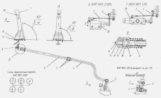
Figure 8. The transmission control unit of the MAZ-5440 car
1,2 - lever; 3, 4, 6 - push; 5, 7, 17 - bolt; 8 - finger; 10 - sleeve; 11 - spring; 12 - slope; 13 - nut; 14 - trunk; 15 - tip; 16 - plate; 18 - switch 19 - ball; 20 - switching mechanisms.
How to adjust the slide on the ointment
Maintenance and adjustment of the YaMZ-238A gearbox for MAZ-64227, MA3-54322 vehicles
Transmission care consists of checking the oil level and replacing it in the crankcase. The oil level in the crankcase must match the control hole. The oil must run hot through all drain holes. After draining the oil, you need to remove the cover at the bottom of the crankcase, into which the oil pump oil separator is attached with a magnet, rinse them well and install them in place. In this case, it is necessary to ensure that the oil line is not blocked by the plug or its gasket.
To flush the gearbox, it is recommended to use 2,5-3 liters of industrial oil I-12A or I-20A in accordance with GOST 20799-75. With the gearbox control lever in neutral position, the engine is started for 7-8 minutes, then it is stopped, the flushing oil is drained and the oil provided by the lubrication map is poured into the gearbox. It is unacceptable to wash the gearbox with kerosene or diesel fuel.
During the operation of the drive gearbox, you can adjust: the position of the lever 3 (see Fig. 47)
shift gears in the longitudinal direction;
the position of the gear lever in the transverse direction - the device for blocking the telescopic elements of the longitudinal rod.
To adjust the angle of inclination of the lever 3 in the longitudinal direction, it is necessary to loosen the nuts on the bolts 6 and, moving the rod 4 in the axial direction, adjust the angle of inclination of the lever to approximately 85° (see Fig. 47) in the neutral position of the gearbox.
The adjustment of the position of the lever in the transverse direction is carried out by changing the length of the transverse link 17, for which it is necessary to disconnect one of the tips 16 and, having unscrewed the nuts, adjust the length of the link so that the gearbox control lever, being in the neutral position against gears 6-2 and 5-1 , had an angle of approximately 90° with the horizontal plane of the cabin (in the transverse plane of the vehicle).
Adjustment of the gearshift locking device should be made as follows:
raise the cab
release pin 23 and disconnect rod 4 from fork 22
clean the earring 25 and the inner rod from old grease and dirt;
push the inner rod until the stop sleeve 15 clicks;
unblock the earring nut 25 and, inserting a screwdriver into the groove of the inner link rod, unscrew it until the angular play of the earring disappears;
without turning the stem 24, tighten the locknut;
check the quality of the fit. When the lock sleeve 21 moves towards the spring 19, the inner rod must extend without sticking to its full length, and when the rod is pressed all the way into the grooves, the lock sleeve must move clearly with a “click” until the sleeve rests against the lower protrusion of the earring.
When adjusting the drive, the following requirements must be observed;
adjustment must be made with the cab raised and the engine turned off;
avoid bends and kinks of external and internal movable rods;
to avoid breakage, connect the stem 4 with the fork 22 in such a way that the hole in the earring for the pin 23 is above the longitudinal axis of the stem 4
check the neutral position of the gearbox with the cab raised by free movement of the lever 18 of the gear change mechanism in the transverse direction (relative to the longitudinal axis of the vehicle). The roller 12 in the neutral position of the box has an axial movement equal to 30-35 mm; feel the compression of the spring.
The gearbox drive adjustments described above must be made when removing and installing the engine and cab.
Possible malfunctions of the gearbox and its drive, as well as ways to eliminate them, are given in Table. 5.