Repair of connecting rod and piston kit
The main defects of the parts of the connecting rod and piston kit are shown in Figure 64.
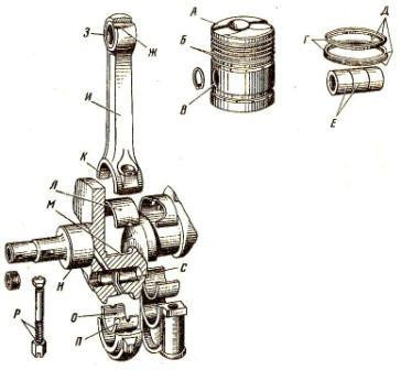
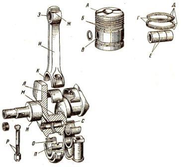
Rice. 64. Possible defects in the parts of the connecting rod and piston kit.
A) - deposits of soot, coke, tar;
B) - groove wear;
B) - wear of the holes for the fingers in the piston;
D) - wear of the outer surface of the rings;
D) - wear of the rings in height;
E) - wear of the fingers on the outside;
D) - wear of the outer sleeve of the connecting rod;
H) - wear of the bushing inside the connecting rod;
I) - Bending and torsion of the connecting rod;
K) - internal wear of the lower head of the connecting rod;
L) - wear on the outer side of the lining;
M) - wear of the connecting rod journal;
H) - The main wear of the neck;
O) - wear of the inner side of the lining;
P) - Destruction of the antenna mounting insert;
P) - Rupture and destruction of the threads of the connecting rod bolts;
C) - Deposition of wear products.
The piston pin is restored by cold expansion (plastic deformation) followed by heat treatment, hydrothermal expansion with simultaneous heat treatment, electroplating (chromium plating, hard iron) methods. After restoration, the piston pins are processed on centerless grinding machines and polished to a normal size, while the surface roughness reaches Ra = 0,16-0,32 microns.
With hydrothermal distribution, HDTV heats the finger in the inductor to a temperature of 790-830 degrees Celsius, then cools it with running water, passing through its internal cavity. In this case, the finger hardens, its length and outer diameter increase from 0,08 to 0,27 mm. Elongated fingers are ground from the ends, then chamfers are removed from the outer and inner surfaces.
Bushings of the upper head of the connecting rod. They are restored by the following methods: thermal diffusion zinc plating with subsequent processing; deposits in the connecting rod; compression followed by the formation of the outer surface of the steel tape by electrocontact welding (the thickness of the tape from low-carbon steels is 0,4-0,6 mm).
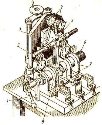
Connecting rod. When the surface under the bushing is worn, the connecting rod is drilled to one of the repair sizes with an interval of 0,5 mm, chamfering at the ends 1,5 mm x 45 degrees. For boring, a URB-VP diamond drilling machine is used, fixing the connecting rod [Figure sixty-five].
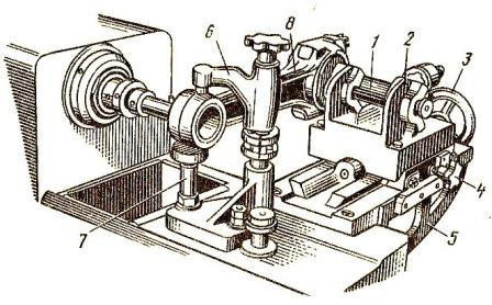
Rice. 65. Fastening the connecting rod to the machine by drilling the bushing of the upper head.
1) — Repair;
2) - Transport prisms;
3) — Steering wheel for vehicle movement;
4) - locking screw of the carriage;
5) — Support;
6) - Stronghold;
7) — Support;
- Connecting rod.
This machine can drill holes with a diameter of 28-100 mm at a speed of 600-975 min-1 and a feed of 0,04 mm/rev.
The distance between the axes of the upper and lower heads is achieved by placing the template between the stops of the bracket (5) and the movable carriage. The correctness of the installation of the connecting rod hole in the vertical plane is checked with a cutter and adjusted with a bracket (7).
Worn inner surfaces of the lower and upper heads of the connecting rods in repair shops are increased by electroplating, drilling and grinding or polishing to normal sizes.
To determine the deviation from parallelism (bending) in the vertical and horizontal (torsion) planes of the axes of the upper head relative to the lower one on carburetor engines, the connecting rod assembly with the cover is checked on a special device [ENG. 66], and for everyone else, call 70-8735-1025.
Rice. 66. A device for the overhaul of connecting rods of automobile engines.
1) - handle for removing the roller;
2) - small mandrel;
3) - sliding guides;
4) – indicator;
5) - rocker;
6) - a large mandrel;
7) - Shelf;
- Connecting rod.
Deviation from parallelism (bending) of the axes of large connecting rod heads is allowed for diesel engines:
D-50 - 0,18mm;
D-240 - 0,05mm;
SMD-17, SMD-18 — 0,15mm;
SMD-60, A-01, A-41 - 0,07mm;
YaMZ-238NB, YaMZ-240B - 0,08mm.
Allowed move:
D-50 - 0,3mm;
D-240 and YaMZ-240NB - 0,08mm;
SMD-17, SMD-18 — 0,25mm;
SMD-60 — 0,07mm;
A-01, A-41 — 0,11 mm;
YaMZ-238NB - 0,1mm.
For automobile engines, the deviation from parallelism of the shafts in all planes is not allowed more than 0,05 mm over a length of 100 mm. To eliminate this defect, it is allowed to edit the connecting rods only after heating their rod with a high-frequency current or a gas burner flame at a temperature of 450-600 degrees Celsius, that is, with heat fixation.
Pistons Restoration of pistons of SMD diesel engines is possible by plasma-arc surfacing. To do this, the piston is cleaned in molten salt at a temperature of 375-400 degrees Celsius for 10 minutes, washed, treated with 10% nitric acid and washed again with hot water to remove varnish and carbon deposits in the grooves. In the piston, the upper groove and head are cast with SVAMG wire and machined.
Packing, assembly. Sets of connecting rods with caps, bots and nuts are selected by weight according to table 39.
Table 39
| Engine make | Weight difference, g | ||
| connecting rods | pistons | connecting rods with piston assembly | |
| A-01M, A-41 | 17 | twenty | 40 |
| YaMZ-240B, YaMZ-238NB | 17 | 10 | thirty |
| SMD-14, SMD-62 and others | 10 | 7 | 22 |
| D-240, D-50 | twenty | 10 | thirty |
| D-37M | 10 | 10 | 25 |
| GAZ-53, ZIL-130 | 8 | 5 | sixteen |
On some of them, the mass is indicated on the outer surface of the lower head, on the cover parallel to the hole for the connecting rod bolt. If it is necessary to equalize the mass, it is necessary to file the metal of the connecting rod along the line of separation of the seals to a depth of 1 mm.
The difference in the masses of parts in the engine assembly during its operation leads to the emergence of unbalanced inertia forces, which causes vibrations and accelerates the wear process of parts.
With the same mass of the connecting rod, the distribution of material along the length must be such that the masses of the lower and upper heads in the connecting rod set are equal (the difference should not exceed ± 3 grams).
Pistons are also selected by size and weight. The mass of the piston is indicated on its bottom. Pistons with sleeves are completed according to the gap between the piston (along the skirt) and the sleeve, designating the groups with the letters of the Russian alphabet (B, C, M, etc.), which are removed on the piston bottom and on the shoulder of the sleeve.
Piston pins are selected according to the size of the group of holes in the piston heads and are marked with paints or numbers 0,1, 0,2, etc.
Bushings according to the outer diameter are selected according to the diameter of the upper head of the connecting rod, and according to the inner diameter - according to the diameter of the pin, taking into account the allowance for machining.
The liners must match the diameter of the crankshaft journals.
Piston rings are selected according to the size of the liners and the clearance in the piston groove, which is allowed for the first ring of diesel engines of the YaMZ, A-41 and SMD-60 types of 0,35 mm (for the rest - 0,27 mm). For the second and third compression segments, the gap is 0,30 mm and 0,20 mm, respectively.
The elasticity of the rings is checked by placing them together in a horizontal position on the platform of a special scale MIP-10-1 [Fig. 67]. The ring is loaded with normal hinge clearance. The force displayed on the dial of the scale must meet the technical requirements.
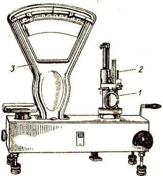
Rice. 67. Checking the elasticity of the piston rings in the device.
1) - Ring;
2) — Device;
3) — Pound.
To check the gap in the gasket, the piston rings are installed in the cylinder strictly in a plane perpendicular to the axis and checked with a feeler gauge. The quality of the fit of the rings to the cylinder wall in the light is also checked [Fig. 68].
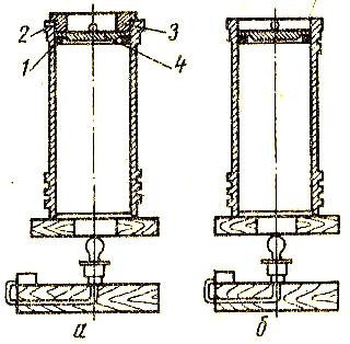
Rice. 68. Checking the clearance of piston rings.
a) - Installation of the ring,
b) - check;
1) - Ring;
2) - Sleeve (support cylinder);
3) - Guide ring;
4) - Instruction.
The gap at the junction of new rings for diesel engines should be 0,6 ± 0,15 mm, permissible without repair - up to 2 mm; for new carburetor engine rings - 0,3-0,7 mm.
The radial play (backlash) between the ring and the cylinder for diesel engines must not exceed 0,02 mm in more than two places along arcs of 30 degrees and not closer than 30 mm from the lock. For torsion and conical rings, the gap is allowed no more than 0,02 mm, for oil scraper rings - 0,03 mm anywhere, but not closer than 5 mm from the lock. Play in the rings of carburetor engines is not allowed.
They also check the height of the ring and the distortion of the end surfaces, which should not exceed 0,05 mm for diameters up to 120 mm and 0,07 mm for rings of large diameter.
assembly and control. The assembly of the connecting rod and piston kit begins with pressing the bushings into the upper head of the connecting rod with an interference fit of 0,03-0,12 mm for diesel engines of different brands, 0,14 mm for carburetor engines. The connecting rod is installed on the URB-VP diamond drilling machine in the same way as shown in Figure 65, then the bushing is drilled with an allowance:
rolled 0,04-0,06mm,
for turning by 0,08-0,15 mm or reaming by 0,05-0,08 mm relative to the normal diameter of the piston pin.
The bushings are rolled by pulse rolling on a vertical drilling machine, bored under a mechanically driven press with a continuous mandrel feed [Fig. 69], lubricated with diesel fuel.
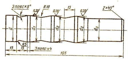
Rice. 69. Dorn of the bushing of the upper head of the connecting rod.
d = D – 0,3;
d1 = D (-0,02 / -0,03);
d2 = D (-0,09 / -0,07);
d3 = D – 3;
D = piston pin nominal diameter.
Then the deviation from the parallelism of the axes of the holes of the bushing and the lower head of the connecting rod is controlled according to the technical requirements. In this case, editing the connecting rod is not allowed. Next, the lower head of the connecting rod is assembled with bushings, a cover and bolts. The bolts should enter the holes with light blows from a 200-gram hammer.
The connecting rod oil channels are flushed and purged with air. The pistons must be heated in an OKS-7543 electrical cabinet or in an oil-water bath at a temperature of 80-90 degrees Celsius, then connected to the connecting rod with a piston pin in a vice.
The assembled assembly is installed on the control plate so that the piston touches any point on the surface of the plate. With a wedge-shaped gap of more than 0,1 mm over a length of 100 mm (measured with a probe), the kit is disassembled, the parts are checked, the defect is identified and eliminated.
The piston pin in the piston bosses is fixed with spring locks. Before installing the rings, check the taper of their outer surface on the control plate using a square.
Rings are installed on the piston with a smaller diameter up (compression, undercut up) eight *