Gas distribution mechanism of the engine, design and principle of operation
Content
The gas distribution mechanism (GRM) is a set of parts and assemblies that open and close the intake and exhaust valves of the engine at a given point in time. The main task of the gas distribution mechanism is the timely supply of air-fuel or fuel (depending on the type of engine) to the combustion chamber and the release of exhaust gases. To solve this problem, a whole complex of mechanisms works smoothly, some of which are controlled electronically.
How is the timing
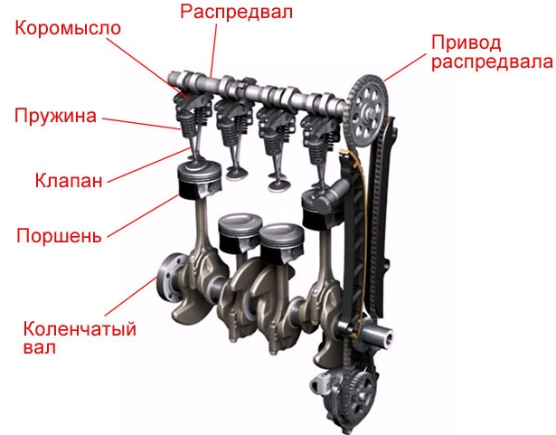
In modern engines, the gas distribution mechanism is located in the engine cylinder head. It consists of the following main elements:
- Camshaft. This is a product of complex design, made of durable steel or cast iron with high precision. Depending on the design of the timing, the camshaft can be installed in the cylinder head or in the crankcase (currently this arrangement is not used). This is the main part responsible for the sequential opening and closing of the valves.
The shaft has bearing journals and cams that push the valve stem or rocker. The shape of the cam has a strictly defined geometry, since the duration and degree of opening of the valve depends on this. In addition, the cams are designed in different directions to ensure alternate operation of the cylinders.
- Drive unit. Torque from the crankshaft is transmitted through the drive to the camshaft. The drive differs depending on the design solution. The crankshaft gear is half the size of the camshaft gear. Thus, the crankshaft rotates twice as fast. Depending on the type of drive, it includes:
- chain or belt;
- shaft gears;
- tensioner (tension roller);
- damper and shoe.
- Intake and exhaust valves. They are located on the cylinder head and are rods with a flat head at one end, called a poppet. Inlet and outlet valves differ in design. The inlet is made in one piece. It also has a larger platter to better fill the cylinder with fresh charge. The outlet is usually made of heat-resistant steel and has a hollow stem for better cooling, as it is exposed to higher temperatures during operation. Inside the cavity is a sodium filler that easily melts and removes some of the heat from the plate to the rod.
The valve heads are bevelled to provide a tighter fit in the holes in the cylinder head. This place is called the saddle. In addition to the valves themselves, additional elements are provided in the mechanism to ensure their proper operation:
- Springs. Return the valves to their original position after pressing.
- Valve stem seals. These are special seals that prevent oil from entering the combustion chamber along the valve stem.
- Guide bushing. Installed in the cylinder head housing and provides precise valve movement.
- Rusks. With their help, a spring is attached to the valve stem.

- Pushers. Through the pushers, the force is transmitted from the camshaft cam to the rod. Made from high strength steel. They are of different types:
- mechanical - glasses;
- roller;
- hydraulic compensators.
The thermal gap between the mechanical pushers and the camshaft lobes is manually adjusted. Hydraulic compensators or hydraulic tappets automatically maintain the required clearance and do not require adjustment.
- Rocker arm or levers. A simple rocker is a two-arm lever that performs rocking movements. In different layouts, the rocker arms can work differently.
- Variable valve timing systems. These systems are not installed on all engines. More details about the device and the principle of operation of CVVT can be found in a separate article on our website.
Description of the timing
The operation of the gas distribution mechanism is difficult to consider separately from the operating cycle of the engine. Its main task is to open and close valves in time for a certain period of time. Therefore, on the intake stroke, the intake opens, and on the exhaust stroke, the exhaust opens. That is, in fact, the mechanism must implement the calculated valve timing.
Technically it goes like this:
- The crankshaft transmits torque through the drive to the camshaft.
- The camshaft cam presses on the pusher or rocker.
- The valve moves inside the combustion chamber, allowing access to fresh charge or exhaust gas.
- After the cam has passed the active phase of action, the valve returns to its place under the action of the spring.
It should also be noted that for a full cycle, the camshaft makes 2 revolutions, alternately opening the valves on each cylinder, depending on the order in which they work. That is, for example, with a 1-3-4-2 operation scheme, the intake valves on the first cylinder and the exhaust valves on the fourth will open simultaneously. In the second and third valves will be closed.
Types of gas distribution mechanism
Engines may have different timing schemes. Consider the following classification.
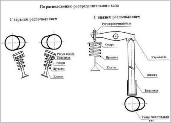
By camshaft position
There are two types of camshaft position:
- bottom;
- top.
In the lower position, the camshaft is located on the cylinder block next to the crankshaft. The impact from the cams through the pushers is transmitted to the rocker arms, using special rods. These are long rods that connect the pushrods at the bottom to the rocker arms at the top. The lower location is not considered the most successful, but has its advantages. In particular, a more reliable connection between the camshaft and the crankshaft. This type of device is not used in modern engines.
In the top position, the camshaft is in the cylinder head, just above the valves. In this position, several options for influencing the valves can be implemented: using rocker pushers or levers. This design is simpler, more reliable and more compact. The upper position of the camshaft has become more common.
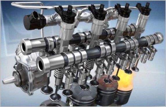
By number of camshafts
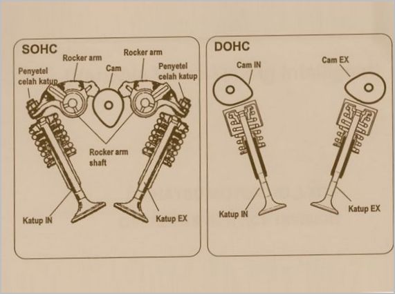
In-line engines can be equipped with one or two camshafts. Engines with a single camshaft are designated by the abbreviation SOHC(Single Overhead Camshaft), and with two - DOHC(Double Overhead Camshaft). One shaft is responsible for opening the intake valves, and the other for the exhaust. V-engines use four camshafts, two for each bank of cylinders.
By number of valves
The shape of the camshaft and the number of cams will depend on the number of valves per cylinder. There may be two, three, four or five valves.
The simplest option is with two valves: one for intake, the other for exhaust. A three-valve engine has two intake and one exhaust valves. In the version with four valves: two intake and two exhaust. Five valves: three for intake and two for exhaust. The more intake valves, the more air-fuel mixture enters the combustion chamber. Accordingly, the power and dynamics of the engine are increased. To make more than five will not allow the size of the combustion chamber and the shape of the camshaft. The most commonly used four valves per cylinder.
By drive type
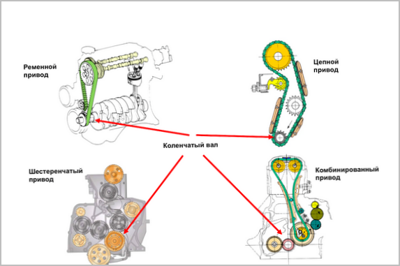
There are three types of camshaft drives:
- Gear. This drive option is only possible if the camshaft is in the lower position of the cylinder block. The crankshaft and camshaft are driven by gears. The main advantage of such a unit is reliability. When the camshaft is in the top position in the cylinder head, both chain and belt drive are used.
- Chain. This drive is considered more reliable. But the use of the chain requires special conditions. To dampen vibrations, dampers are installed, and the chain tension is regulated by tensioners. Several chains can be used depending on the number of shafts.
The chain resource is enough for an average of 150-200 thousand kilometers.
The main problem of the chain drive is considered to be a malfunction of the tensioners, dampers or a break in the chain itself. With insufficient tension, the chain during operation can slip between the teeth, which leads to a violation of the valve timing.
Helps to automatically adjust chain tension hydraulic tensioners. These are pistons that press on the so-called shoe. The shoe is attached directly to the chain. This is a piece with a special coating, curved in an arc. Inside the hydraulic tensioner there is a plunger, a spring and a working cavity for oil. Oil enters the tensioner and pushes the cylinder to the correct level. The valve closes the oil passage and the piston maintains the correct chain tension at all times. Hydraulic compensators in a timing belt operate on a similar principle. The chain damper absorbs residual vibrations that have not been dampened by the shoe. This guarantees perfect and precise operation of the chain drive.
The biggest problem can come from an open circuit.
The camshaft stops rotating, but the crankshaft continues to rotate and move the pistons. The bottoms of the pistons reach the valve discs, causing them to deform. In the most severe cases, the cylinder block may also be damaged. To prevent this from happening, double-row chains are sometimes used. If one breaks, the other continues to work. The driver will be able to correct the situation without consequences.
- belt.The belt drive does not require lubrication, unlike the chain drive.
The resource of the belt is also limited and averages 60-80 thousand kilometers.
Toothed belts are used for better grip and reliability. This one is more simple. A broken belt with the engine running will have the same consequences as a broken chain. The main advantages of a belt drive are ease of operation and replacement, low cost and quiet operation.
The operation of the engine, its dynamics and power depend on the correct functioning of the entire gas distribution mechanism. The greater the number and volume of cylinders, the more complex the synchronization device will be. It is important for each driver to understand the structure of the mechanism in order to notice a malfunction in time.