Links, links, links?
Content
Encounters with Electrochemistry Part 5
During previous meetings, we have seen many examples of galvanic cells - those of only historical significance and others in use today. The world of cells is very rich, so it's time to introduce systems different from those shown so far.
Non-metals can also be semi-cells
First, an experiment that requires two graphite electrodes from spent Leclanchet elements, zinc bromide ZnBr2, power supply (such as a 4,5V battery) and an indispensable voltage meter. In the home laboratory, of course, we will not find the recommended zinc salt, but in our case it will be successfully replaced by a mixture of potassium bromide KBr and zinc sulfate (VI) ZnSO.4. We assemble a set consisting of two graphite sticks, fasten it to the board so that the electrodes are partially immersed in the glass.
We attach pieces of wires to the electrodes, preferably with a soldering iron (therefore, when removing them from the old battery, leave brass “caps” on the graphite rods). We will also make a diaphragm from a piece of cardboard with dimensions adapted to a beaker with a capacity of 50-100 cm.3 (cardboard can be additionally pierced with a pin).
Now we dissolve some of the mentioned salts in water, and then fill the glass with the prepared solution (concentration 5-10%). Place the rack with electrodes on the edge of the vessel, and attach the ends of the wires to the brass plates of a flat battery (polarity does not matter at the moment) and observe the built system.
Almost immediately, a silver-gray shiny layer is deposited on the electrode connected to the negative terminal of the battery. Made from metallic zinc. A yellowish-brown color of the solution is visible near the second electrode connected to the positive pole of the battery. Free bromine is colored near the graphite rod. After about 5 minutes, disconnect the wires from the battery terminals. Using a voltmeter, measure the voltage ("minus" of the meter is connected to the electrode covered with a layer of metal).
Without going into the processes that occur during electrolysis (we will discuss them at one of the following meetings), we can conclude that the created cell consists of two electrodes: zinc (metal zinc deposited on graphite in a solution of Zn2+) and bromine (a solution of free ions of bromine and bromide Br?). Carbon is only a conductor of electricity (in practice, non-reactive substances under certain conditions, such as graphite, platinum, are often used as electrode materials).
Let's connect the current receiver to the electrodes? a light bulb with an operating voltage of 1,5 V (in this case, the polarity of the connections also does not matter). As energy is extracted from the system, we observe the gradual disappearance of the metal deposit on one electrode and the yellowish color on the other. Previously released substances react, restoring their original state. The reaction is indirect with the transfer of electrons through the connecting wire. This is the essence of galvanic cells.
What reactions took place in our system? For the zinc electrode, we can certainly give the process equation:
(-) Zn0 ? zinc2+ + 2e-
At the second electrode, free bromine is reduced to bromine anions:
(+) No.2 + 2e- , 2 pcs-
Thus, the cell scheme is as follows (we omit the potassium and sulfate (VI) ions, which do not participate in the reactions):
(-)С, Zn | ZnBr2aq? ZnBr2aq | C(+)
We don't need to use aperture in the cell. However, its use will prevent bromine from migrating near the zinc-coated electrode and directly reacting between the cells.
Non-metals form half-cells like metallic elements. It is only necessary to use a conductor immersed in an appropriate solution, which will participate in the transfer of electrons. For halogens, the standard potentials are as follows (the electrode reaction is similar to that given for bromine):
| Half cell | F2/F? | Cl2/Cl? | Br2/ BR? | I2/I? |
| E0 [V] | + 2,87 | + 1,36 | + 1,07 | + 0,54 |
In the case of fluorine, the potential value (the highest of all the half-cells determined) was calculated, not measured. The reason, as in the case of alkali and alkaline earth metals, is the reaction of the active element with water.
redox cell
For the next experiment, we will prepare the following solutions: iron (III) chloride, FeCl3 with a concentration of 5%, potassium iodide KI with a concentration of 10% and a water-starch suspension. Mix a few cm in a test tube3 salt solutions, and after a while add a few drops of starch suspension. The dark blue color of the contents indicates the presence of free iodine. The reaction is written by the equation:
2Fe3+ + 2i- ? 2Fe2+ + me2
iron (III) cations oxidize iodide anions to a free element, reducing to iron (II) ions.
A change in the color of the starch indicator confirmed the presence of iodine particles, but are Fe cations really formed?2+? Let's test this hypothesis. A characteristic test for the detection of iron(II) cations is the reaction with potassium hexacyanoferrate(III) K3[Fe(CN)6], commonly known as potassium ferricyanide. The compound forms red crystals, in contrast to the potassium ferrocyanide of the same name (potassium (II) hexacyanoferrate K4[Fe(CN)6]) with yellow crystals ? let's not confuse these two relationships. We repeat the previous experiment, but instead of a starch suspension, we add a few drops of a 1% solution of potassium ferricyanide. Again, the contents of the reaction vessel turn dark blue due to a complex combination called Turnbull's blue:
3Fe2+ + 2[Fe(CN)6]3- ? Faith3[Fe(CN)6]2
I recommend that unbelievers conduct a test with salts of ferrous and ferric iron. We get a blue tint only in the case of the first one.
Now, in two small beakers with a capacity of 50-100 ml, pour several solutions of iron (III) chloride and potassium iodide.3. In each of the vessels, immerse a graphite electrode with a wire attached (placed on a suitable stand so that it does not fall into the glass). Also, add a little starch suspension to a vessel with a solution of potassium iodide. To create a cell, you will also need an electrolytic key (made during one of the previous meetings? A strip of blotting paper soaked in a concentrated solution of KNO is enough.3). The ends of the leads from the electrodes are connected to the terminals of a universal meter installed to measure voltage.
We determine the polarity of the voltmeter connections ourselves on the basis of an analysis of the equation for the reaction of iron (III) cations with iodine anions, we note which of the ions they give and which receive electrons. The meter readings confirm the operation of the galvanic cell. Then we switch the device to the current measurement. It is small (on the order of several tens of mA), so we do not need to use any additional receiver (for example, a light bulb) to protect the device from damage. The formation of a dark blue color around the electrode immersed in a beaker with a solution of potassium iodide testifies to the course of the reaction in the system. When do we add a little potassium ferricyanide solution to an iron(III) salt shaker? also in it. Let us write down the equations of the processes occurring in the glasses:
(-)2I- ? 2 + 2e-
(+)2Fe3+ + 2e- ? 2Fe2+
and cell diagram:
(-) With | CIaq || FeCl3aq | C (+)
The same reactions take place in the cell as after mixing the substrates in a test tube (it is enough to add the anodic and cathodic processes by the sides), and the spatial separation of the transformations makes it possible to use the energy of electrons transferred between the halves of the cell.
The cell we are building is called a redox cell. The name is common but misleading. After all, we know that the processes of oxidation and reduction occur in each link. How to determine the direction of a redox reaction (carried out both in a cell and in a test tube)? The method is simple:
1. In physical and chemical tables, do we find the standard potentials of the corresponding half-cells? for Fe system3+/ Faith2+ this is +0,77 V; for me2/I?: +0,54V.
2. A system with a higher potential is an oxidizing agent in the reaction (cell-cathode), and a half-cell with a lower potential? the anode of the cell, i.e. the reducing agent.
3. However, it should be remembered that for systems with a small difference in the values of standard potentials, in some cases, the roles can be reversed (actual potentials depend, among other things, on the concentration of reagents).
Fuel cell
We will assemble the system from the first experiment, replacing only the solution of potassium bromide and zinc sulfate (VI) with a 10% solution of sulfuric acid (VI) H2SO4. After 1-2 minutes of electrolysis (occurring with the release of gas on the electrodes), turn off the power source and carefully, so as not to remove gas bubbles from the graphite surface, measure the voltage with a voltmeter. Link created! After switching the device to the current measurement mode, one can observe the disappearance of gas bubbles on the surface of the graphite electrodes during the reaction. Without going into details of the process that caused the deposition of free oxygen and hydrogen on the electrodes, the reactions in the cell are as follows:
(-)2H2? 4 hours+ + 4e-
(+) The2 + 4H+ + 4e- ? 2h2O
In total, the reaction of the synthesis of water from the elements takes place.

The constructed system is a fuel cell model. Direct conversion of the energy of the reaction between the fuel and the oxidizer into electricity is extremely beneficial from the point of view of the economy of the process? There is no need to convert the heat of combustion into steam energy, which only drives the turbines. Not surprisingly, such systems are designed to solve energy problems (and the waste is clean water). However, the price of building materials and the need to produce hydrogen are a major hurdle.
Although fuel cells have been used to generate electricity in the most technologically advanced areas such as space flight (in some industries, costs play a secondary role), their history is very long. The first working prototype of the hydrogen-oxygen cell was built by British inventor William Robert Grove in 1839.
The article presents several types of links, different from those discussed in previous meetings. Like the rest of the episodes? only the problems of these systems, which are important not only as a source of energy, are outlined. However, the need to maintain a reasonable text size makes it impossible to discuss many interesting topics related to links (I encourage interested readers to search for information on their own). In the next episode of the cycle, we will analyze the table of half-cell potentials. There will also be offers of interesting experiences.
electronic application
redox cell
Each electrochemical cell undergoes oxidation (at the anode) and reduction (at the cathode). However, in chemical jargon, redox cells are referred to as a specific type of system.
For the experiment, solutions of potassium iodide KI and iron (III) chloride FeCl are required.3 and an aqueous suspension of starch (potato flour). You will also need an electrolytic key filled with a concentrated solution of potassium nitrate (V) KNO3. If we do not have a key, it is enough to fold several times a strip of tissue paper or a cotton thread soaked in a solution of potassium nitrate.
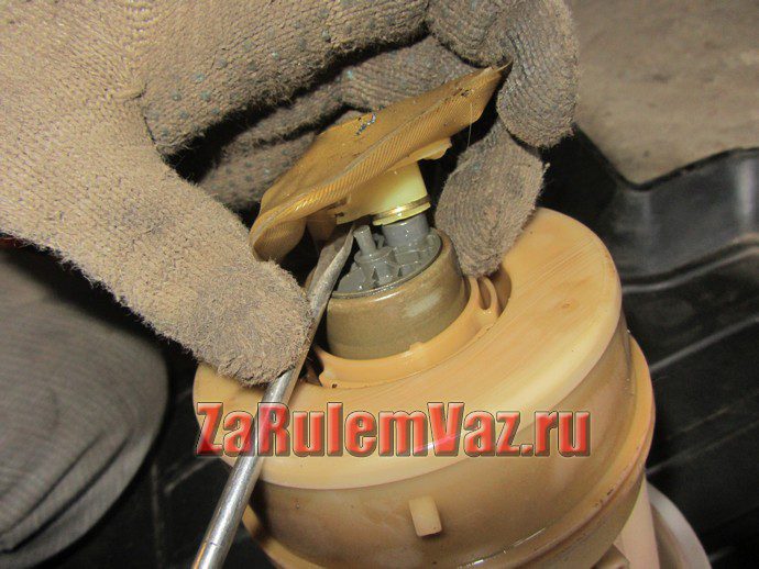
We will use graphite rods from used Leclanche cells as electrodes (photo 1). Short-circuit the ends of the electrodes with a wire and immerse them in beakers with KI solutions (with the addition of starch slurry) and FeCl.3. Additionally, we combine solutions in glasses with an electrolytic key or one of its substitutes (photo 2). After some time, purple streaks begin to appear in the beaker with potassium iodide solution (photo 3), gradually staining the vessel in a dark color (photo 4 and 5). It is a characteristic product of the combination of free iodine molecules with starch molecules. Iodine was formed as a result of the oxidation of iodide anions at the anode of the cell:
(-) Anode: 2I- ? 2 + 2e-
At the second electrode (cathode), iron (III) ions were reduced:
(+) Katoda: 2Fe3+ + 2e- ? 2Fe2+
The redox cell created in the experiment has the following scheme:
(-) C | CIaq || FeCl3aq | C (+)
where the carbon symbol C denotes a graphite electrode and || ? electrolytic key. The overall reaction in the system is the oxidation of anions I- by Fe cations3+:
2Fe3+ + 2i- ? 2Fe2+ + me2
redox cell
concentration cell
For the second experiment you will need: a solution of copper sulphate (II) CuSO4, copper electrodes, electrolytic key filled with a concentrated solution of potassium nitrate (V) KNO3 and universal counter. Fill one of the beakers with the CuSO solution.4and another with the same dilution of 1:100 (for example, 0,5 cm3 the solution taken from the first glass, add water to a volume of 50 cm3) (photo 6). After immersing the copper wires in glasses and closing the circuit with an electrolytic key, measure the voltage between the electrodes of the cell. It is small? about a dozen or several tens of millivolts (photo 7).
Copper dissolution and precipitation reactions occur on the electrodes:
(-) Anode: Cu0 ? With2+ + 2e- (less concentrated solution)
(+) Cathode: Cu2+ + 2e- ? With0 (more concentrated solution)
After adding the equations of both electrode processes, it turns out that no chemical reaction occurs in total! The driving force of the cell is only the desire of the system to equalize the concentrations in both glasses.