Replacing the speed sensor GAZ 3309
Content
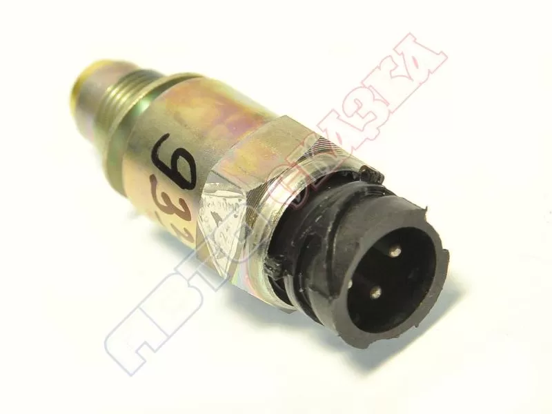
The speed sensor (abbreviated as DS or DSA) is installed on all modern cars and serves to measure the speed of the car and transfer this information to the computer.
How to replace the speed sensor (DS)
- First of all, you need to turn off the engine, cool it and de-energize the system by removing the battery terminals. This is very important to avoid injury during repair work;
- if there are parts that impede access to the detector, they must be disconnected. But, as a rule, this device is in stock;
- the cable block is disconnected from the DC;
- after which the device itself is directly disassembled. Depending on the brand of the machine and the type of sensor, it can be fastened with threads or latches;
- a new sensor is installed in place of the faulty sensor;
- the system is assembled in the reverse order;
- it remains to start the car and make sure that the new device is working. To do this, it’s enough to drive a little: if the speedometer readings correspond to the real speed, then the repair was carried out correctly.
When buying a DS, it is necessary to strictly observe the brand of the device in order to install exactly the sensor model that will work correctly. For some of them you can find analogues, but you need to carefully study each of them to make sure they are interchangeable.
The process of replacing the detector itself is not complicated, but if you do not know how to replace it, or if a novice motorist has a problem, you should contact a service station and entrust your car to specialists.
In any case, before starting to repair a car, you should carefully study the instructions and manuals, as well as strictly follow the recommendations and schemes described in the manuals.
Signs of a malfunctioning speed sensor
The most common sign that a speed sensor has failed is idle problems. If the car stalls at idle (when shifting gears or coasting), among other things, be sure to check the speed sensor. Another sign that the speed sensor isn't working is a speedometer that doesn't work at all or doesn't work properly.
Most often, the problem is an open circuit, so the first step is to visually inspect the speed sensor and its contacts. If there are traces of corrosion or dirt, they must be removed, the contacts cleaned and Litol applied to them.
Checking the speed sensor can be done in two ways: with the removal of the DSA and without it. In both cases, a voltmeter will be required to check and diagnose the speed sensor.
The first way to check the speed sensor:
- remove speed sensor
- determine which terminal is responsible for what (the sensor has three terminals in total: ground, voltage, pulse signal),
- connect the input contact of the voltmeter to the pulse signal terminal, ground the second contact of the voltmeter to a metal part of the engine or car body,
- when the speed sensor rotates (for this you can throw a piece of pipe on the sensor shaft), the voltage and frequency on the voltmeter should increase.
The second way to check the speed sensor:
- raise the car so that one wheel does not touch the ground,
- connect the contacts of the voltmeter to the sensor in the same way as described above,
- spin the raised wheel and control the change in voltage and frequency.
Please note that these test methods are only suitable for a speed sensor that uses the Hall effect in operation.
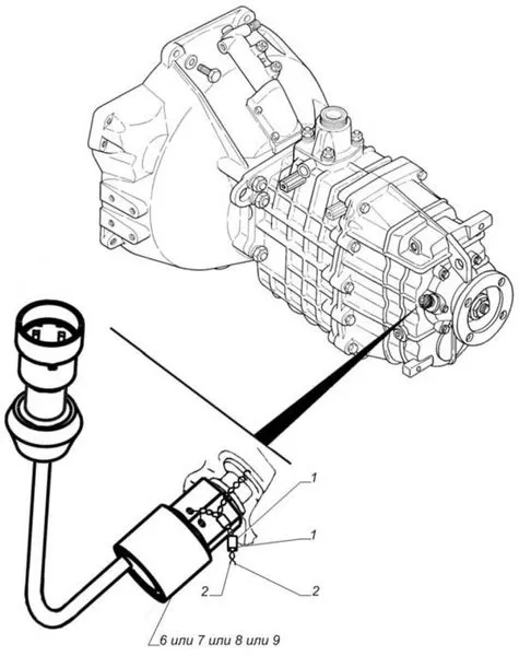
Gas speed sensor 3309 where is it
Almost any tachograph installation office will replace your mechanical speedometer with an electronic yes. But the cost of this service will be inadequate. By the way, the office closest to me puts a tachograph for almost 40 sput. Another 9 laps will change the speedometer. No, better by yourself.
A bit unpleasant: there are speedometers, speed sensors. I don't know which speedometer will suit me and which speed sensor it will work with. Speedometer connection diagrams - they are not on the Internet. Meanwhile, the replacement of a mechanical speedometer has a very rational grain: there will be no speedometer cable that freezes in winter and jams throughout the year. The new speedometers have a normal human backlight, in which you can see the speed readings at night and the high beam indicator is much more noticeable.
The speedometer for the jeep should be 24 volts, the diameter of its body is 100 mm.
From my experience it became clear that the speedometer must be adjustable; It will also come in handy, because if I ever change to a different wheel size, the speedometer reading can be corrected. Further investigation gave another criterion: the speedometer should not be with a CAN bus. There was this rubber on gas, there is nothing to start with. That is, it is possible, but for a speedometer with a CAN bus, there is only one sensor, the connection diagram for which is not easy to find. At the same time, the tachograph can work with almost any speed sensor, and if you have a truck with ABS, then you can do without a speed sensor: take a signal from the ABS sensor of one of the wheels.
Having picked up on the Internet, he gave catalog numbers of speedometers compatible with ANZHS.453892.006 (84.3802.000-01) - for GAZ 4795 Optimus, from which he chose the product of Vladimir Avtoribor 87.3802 - mainly due to the fact that he is more common on sale and he has a friend me on the old Forester red arrow with a green scale. It is also customizable, and, valuablely, its instruction manual is posted on the Internet. Everything you need is there: how to connect, how to reassign.
Speed sensors with their abundance and lack of technical documentation caused a stir. I even strangled my personal toad and bought a few more than I needed for experiments. The first batch consisted of inexpensive sensors in a plastic case. Those in the photo give 6 pulses per revolution, so it looks like the speedometer is set initially.
It quickly became clear that they were all implemented with the participation of a Hall sensor, that the circuits may not be the same for different types of sensors, but they all work when connected to a 12-volt or 8-volt power supply, the one that produces the speedometer. The main selection criterion, perhaps, is the sensor connector. The one on the left in the picture is better not to take, I did not find the connecting part of the connector on sale. Otherwise, the connector, which is known for the carburetor eight, its “mother” can be found in stores or in China. Also, if you take the sensor 2111.3843, its contacts are signed on the +A- connector. Driving on the track after that becomes an easy task.
Plastic sensors are not bad, but they have one drawback: they cannot be screwed into the place where the flexible shaft of the speedometer drive is fastened; the sensors have a 16x1,5 thread, the counterpart on the transfer case is 20x1,5. But if you can't screw up, maybe you can screw up? We take a 20x1,5 nut, straighten the edges of the speed sensor hexagon and screw it into the nut, trying, if possible, to do it coaxially. A slight distortion of parts is not very critical, but not particularly desirable. Then cut 7mm of thread on the sensor and screw it back onto the nut. Tighten the nut instead of the speedometer cable. Everything will be fine, the turnover there is small.
Winding a tachograph or winding a speedometer is often necessary for drivers, companies that work where fuel and lubricants are compensated by the norms of a certain fuel consumption per kilometer, unfortunately. But, on the road, this does not always allow you to correctly calculate the real consumption, and in the end, the driver will have to pay for part of the fuel out of his own pocket, since fuel consumption when driving in traffic jams is much higher than usual. To prove something, the employer actually used up more fuel and lubricants, it's simply useless than it should be decided by the rules. For this situation, the winding or speedometer of the tachograph of GAZ cars is used.
Speedometers of the Vladimir Avtopribor plant
Speed limit signaling device Variable PPS Sealing cap KAMAZ, Electronic speedometer PAZ with speed sensor and harness (6 m) 81.001-3802000 Rated voltage 24 V Total and daily mileage counter Setting the speed limit Signaling speed exceeding Variable PPS Coverage coefficient Sealed Speed sensor 4202.3843010 Electronic speedometer KAMAZ with speed sensor and harness (9m) 81.003-3802000 Rated voltage 24 V Total and daily odometer Speed limit setting Alarm before exceeding. PPP Variable Rate Coefficient Necessity
How it works Before
speedometer than to say how to tighten the winding or odometer readings, let's figure out on what principle the speedometer works on the Gazelle. The principle of operation of the mechanism is to measure the speed of the vehicle by mechanically connecting it to the output of the gear shaft pulley. The latter receives the driving wheels.
The axle can give a true measurement of the speed of movement, the wheels of the car will allow a more accurate measurement. This is because the toothed pulley is farther from the gearbox and the wheels are closer together, and the speed at which it rotates is set to the final speed after the gearbox. The spinning pulley speed can be the same in both first and fourth gear, but the speed difference can be enormous.
In a transmission, the output pulley contains a gear that rotates with the pulley. The gear is connected by a cable to the speedometer transmission. In the scheme, a strong cable is a cable located inside a protective rubber casing. One end of the cable is installed in a special hole and fixed on the drive gear. When the gear turns, the cable turns with it.
the end of the second cable is connected to the instrument at the control end. The shield has a magnet in the form of an axis, which is installed near the steel drum, but does not come into contact with the drum, is fixed on the needle and transmits readings to the appropriate scale. When the vehicle is stationary, the needle cable is held at zero by a small coil spring.
Instrument rewinding
So spinning like a speedometer on a Gazelle yourself? You can finish and finish reading according to various schemes, we will consider each of them separately.
Homemade ways
If you don’t know how, then you can use a simple method, which is to interfere with the operation of the odometer. Before winding the odometer, prepare a punch. If necessary, use pliers to remove the instrument panel and partially remove it by opening the glass and removing the odometer. With the help of an awl and pliers, the race is twisted into a twisted one, the automatic odometer is installed in its place at the ordered control, and the shield is connected to the on-board network.
Ready options
if you are the owner of a new model, you can use the ready-made Gazelle Business speedometer equipped with an electronic clockwork odometer. How to wind up a speedometer with such a device? There is nothing difficult in this.
Before winding it, it is necessary to find the OBD-2 connector on the car, to which you need to connect the twist:
- First connect the device to the socket, the ignition must be turned off.
- after activating the mode, turn on the ignition, the control lamp on the handle should light up, thanks to which you can adjust the winding speed of the readings. If the speed is slow or non-existent, use After.
- sub-modes of how rewind works, you can leave the speedometer full, turn off the ignition and turn off the turn. The nuances of operating the device may differ depending on the manufacturer, so follow the Instructions when using the device.
speedometer instructions are usually among those that evaluate the quality and timing of maintenance by criteria, more precisely speaking about a car, it refers to an odometer, an integral part of an instrument that measures the distance traveled, does not violate the common name of the device, it will continue to be called so. Often for a number of reasons, sometimes subjective, it is necessary to turn the speedometer back, changing the path traveled by the car.
About speedometer types
Before you learn how you can change the readings of such a device with your own hands, you should consider its capabilities. There are several fundamentally different types of mechanics:
- speedometers;
- electromechanical;
- electronic.
Mechanical speedometer
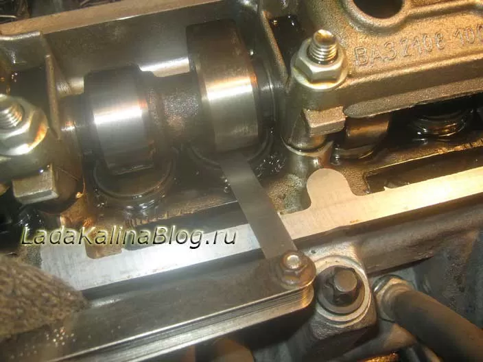
Gearbox The revolutions are transmitted by cable directly to the device, where the revolutions are measured and converted into revolutions. For this, a reducer with a preselected conversion factor is used. How this is done, the photo will help to understand.
In fact, it turns out that one revolution at the output of the gearbox corresponds to a certain number of meters traveled. This rotation of the output shaft is sensed by special discs (used by the instrument) with numbers indicating the measured distance.
Speedometer Electromechanical
This type of device is a further development of the device described above. In many cases, the cable was the main source of errors and was replaced. The speed sensor installed on the gearbox was connected to the device. Impulses from it came to the engine with the appropriate control, rotary gearbox. Otherwise, the operation of such a speedometer was no different from a mechanical one, resembling it in appearance and appearance.
Electronic speedometer
This type is installed on modern cars. In this case, the number of revolutions of the wheel is measured. Knowing the length of its circumference, it is not difficult to translate the number of revolutions to the distance traveled. The result is shown in Why.
Do the LCDs change the speedometer readings?
winding the speedometer is possible for various reasons, for example:
- increase in fuel costs. More mileage allows you to write off more fuel. And it's not necessarily a postscript-related scam. The fact is that on an old worn-out car, fuel consumption sometimes exceeds the established norms. Thus, the higher costs must be offset.
- When replacing the engine, the instrument panel. In this case, it is necessary to bring the speedometer readings in line with the new ones.
- disc usage conditions other than those recommended. At the factory, the diameter may be larger or smaller than specified for the standard, respectively, the wheels will cause a permanent error in calculating the distance traveled. Here, the winding allows you to remove it, including those made by yourself.
How is the speedometer rolled up?
quite a complex and ambiguous question. All types depend on the speedometer (you can use your own methodology for each), as well as on the date of manufacture of the car. Below we consider some possible approaches to solve this problem.
Despite the fact that devices of this type remained only on old machines, it is much more difficult to work with them, purely mechanical. Here, as in other situations discussed below, it is necessary to separate the two windings:
How to wind up an electronic
Therefore, to change its readings, it may be necessary not only to supply additional speed pulse sensors, but also to reprogram some blocks. And besides, again, depending on the characteristics of the car, different for UAZ, VAZ, Gazelle, etc., as well as the year of manufacture, the method of access to the speedometer will be determined.
Therefore, it is quite difficult to do such work with your own hands, although no one says that this is impossible. But this will require the use of special electronic devices.
Due to the existing variety of machines and methods for processing speedometer data, several different options have been created that allow you to correct the readings of the distance traveled. The circuit of such a device can be made discrete both in terms of elements and microprocessor systems, but all finished products are divided into the following types:
Therefore, thanks to this, it is possible to adjust the contents of the desired cells to achieve the desired result in memory. To detect with diagnostic equipment that the memory cells have been changed, Buy.
Pulse twist to OBDII
device This is for use with non-CAN bus equipped foreign vehicles. This device is connected via a special OBDII diagnostic connector. In this case, the speedometer receives a sequence of pulses that imitate a sensor with speed signals, due to which the readings of the distance traveled change.
Speed generator
Suitable for machines equipped with work. Its ABS is based on the control of speed and wheel slip. A tornado connected to the corresponding connector imitates the operation of the wheels, and the controller, having received this information, begins to change the speedometer readings.
It is also worth noting that the model of the car and the date of its release are decisive when choosing a speedometer winding device. In some cases, the speedometer readings on a VAZ or UAZ will not be the same as on a MAZ or KAMAZ.
You can make a winder yourself or buy it ready-made, but the most important thing is to determine whether it can be used on this machine. If used incorrectly, it can simply burn electronics.
No matter how it sometimes seems, it is not the turn on the contrary that becomes strange, but the turn of the speedometer, its turn. There are a number of reasons for this, both objective and subjective. More than one device has been created to solve the problem, and you can choose a device that takes into account the release date of a particular one and allows the car to perform this procedure without a twist.
consequences (coil, winder) GAZ 33081 is a special device that allows you to independently increase the car's mileage.
It is completely removable. Does not require installation, does not require configuration. You just need to connect the device and winding will immediately begin.
our mileage is a modern device for cheating car mileage. The device purchased from us does not cause malfunctions in the operation of the GAZ electronic system of the car 33081.
We offer to buy only proven mileage winding, which will work very well and for a long time. In addition, all devices purchased from our store are covered by a free 5-year warranty.
The speedometer corrector can be used on different cars, which is definitely an advantage.
Easy to use and sometimes indispensable.
Krutilka speedometer (coil, winder) 33081 Gas - a device for self-increasing mileage price 2490 rubles. Free shipping. 5 years warranty
Features
Winding speed: 210 km/h connection
270: Separate connection via cigarette lighter
High quality: plastic material
Dimensions: Length 97 mm., Width Height., 26mm 19 mm.
Power supply: 12V from the cigarette lighter
Questions
answers speedometer knob connected?
The diagnostic tool is connected to the socket or through the cigarette lighter, depending on the model of the car. If the car has a CAN bus, then the connection will be made through the diagnostic.
Does mileage increase with connection speed?
The speed of increase in mileage depends on the model of the car, but on average it is about 1700 km/h
What is the difference between CAN Generator and Speed Winder?
The CAN coils are connected to the diagnostic socket, and the data is transmitted through the digital bus generator. Speed CAN connected to the cigarette lighter, the device sends pulses imitating the speed sensor (data is transmitted over the cable that comes from the speed sensor)
I live. If not in Moscow, but in another city, how can I pay for the device? How long does delivery take
I'm sending? The device throughout Russia, payment is made directly at the post office upon receipt of the goods depends. The term depends on the remoteness of the settlement, usually 4-8 days.
After I ship the device to you, I will send you a CMC with a shipping number. So you can always find out where your turn is.
Can the device be used in a package?
No, just get up! When the ignition is on or the engine is running, the vehicle and the instrument send a signal to the speedometer at the same time. This data is different and out of sync with each other, which can lead to errors.
Is mileage recorded on all blocks?
the device simulates the movement of the car and records everyone in these blocks of the car.
What is the difference between restricted device and unlimited device?
The limit can be increased by 50 km, to resume the operation of the device it is necessary to reflash it. Flashing costs 000r The Unlimited device (without a limit) has no restrictions and has the possibility of an additional upgrade for different car brands.
The diesel power supply system, in accordance with the diesel configuration specified in Table 6, consists of: — Common Rail Common Rail injection system, including a fuel pump, injectors, a high-pressure fuel accumulator, crankshaft and camshaft speed sensors), sensors for the state of the working environment (fuel and air pressure and temperature), electromagnetic actuators (fuel pressure regulator, injector solenoid valves), electronic control unit and communication control circuits, control and diagnostic boards; low pressure fuel lines; high pressure fuel lines; intake manifold; manifold; turbocharger; fuel fine filter; pre-filter*, air filter*, fuel tank* .
In the diesel power system circuit there is a tool that facilitates starting the diesel engine at low ambient temperatures: a glow plug.
* - set by the user.
A schematic diagram of the control and management of the COMMON RAIL power system is shown in Figure 5.
Symbols of the elements of the electrical circuit of the GAZ-3309 car: A8 ′ - preheater; A10 - heater; 81 -
oil pressure sensor; 82 - oil pressure alarm sensor; 87 - coolant temperature indicator sensor;
88 - coolant overheat indicator sensor; 812 - fuel gauge sensor; 819 - air pollution sensor signaling device
Filter; 831 - emergency pressure sensor (1 brake circuit); 832 - emergency pressure sensor (1! brake circuit); 861' — alarm sensor
preheater overheating: 867 - brake fluid level sensor; 897 - pressure sensor (brake circuit); 898 - pressure sensor (n
brake circuit); 899 - emergency piston stroke sensor in the pneumatic booster (1 brake circuit); 8100 - emergency piston stroke sensor in the air motor
left brake circuit); 8101 - Emergency stroke sensor of the right pneumatic booster piston (brake circuit); 025 - electrocorrector control unit
headlights; E1 - headlight left; E2 - Headlight right; Eb - left front lamp; Eb - right front lamp: E9 - repeater
turn indicator to the left; E10 - right turn signal repeater; E11 - Left front contour lamp; 812 - Front contour lamp
right; E16 - cab cover; E27 - Left rear light; E28 - rear right lamp; E29 - reversing lamp; ЕЗ1 - rear light
fog; ЕЗЗ - Circuit of the rear left lamp; E34 - Rear right contour lamp; E35 - engine compartment lamp; ЕЗ7 - clearance lamp
left front side; E38 - Side marker lamp, front right; E39 - left tail light; E40 - side light
right rear side; EbEbZ - glow plugs; 854 ′ — glow plug preheater; E/Z — blocking signaling devices, left; E84 - block
signaling devices on the right; 1:26" - preheater thermal fuse; 1:41 - fuse box; 1:42 - upper fuse box; 1:43-
lower fuse box; 61 - generator; 6265 - rechargeable batteries; H1 - left sound signal; H2 - right sound signal; NC - buzzer
air pressure drop; H7 - signaling device for emergency oil pressure drop; H8 - signaling device for overheating of the coolant; H9' - signaling device
overheating of the starting heater; H11 - signaling device for clogging the air filter; H16 - signaling device for turning on the direction indicators of the tractor; -
H19 - critical fuel level indicator; H20 - high beam signaling device Headlights; NZO - parking brake on indicator; H37′ -
heater operation signaling device; H39 - ABS malfunction indicator; H44 - air pressure gauge backlight
(brake circuit); H45 - backlight lamp for the air pressure level indicator (1! Brake circuit); H47 - illumination of the fuel gauge; H48 - illumination of the current indicator; H54 - signaling device for the discharge of the battery: H56 - signaling device for insufficient brake fluid level; H62 -
front side light lamp; Nbb - speedometer backlight; Hb7 - indicator of the temperature level of the backlight lamp; H68 - backlight lamp
pressure level indicator; H69 - tachometer backlight; H74 - stop lamp; H76 - tail light lamp; H78 - lamp
rear turn signal; НЗО - overall light signaling device; H96 ′ - signaling device for turning on the glow plug of the preheater; H98 -
dipped beam lamp H100 - high beam lamp: H102 - front direction indicator lamp; K1 - additional starter relay; K3 - relay control
wiper; K5 - start blocking relay; K7 - horn relay; K8 - brake signal relay; K1O' - thermal switch
heater; K11 ′ - relay for turning on the plug of the preheater; K12 - turn signal switch; K22′ - master
heater impulses; K64 - relay for turning on glow plugs; K71 - rear fog lamp relay; K74 - relay
engine stop solenoid; M1 - '- starter; M2 - right cabin heater electric motor; M4 - wiper motor; M5 -
windshield washer motor; М7′ — preheater electric motor; M8' - electric motor of the starting fluid pump
heater; M23 - heater electric motor left; M38 - electric drive of the corrector of the left headlight; M39 - electric drive of the right corrector
headlights; mm - engine stop electromagnet; RZ - tachometer; P4 - current indicator: Rb - coolant temperature indicator; P7 - pointer
oil pressure P8 - fuel gauge; P12 - pressure gauge (brake circuit); P13 - pressure gauge (brake circuit); 01 - battery switch
mechanical batteries; 812' - resistance of the starting heater electric motor; 81 - instrument and starter switch; 35 - switch
emergency light signaling; 56 - interior heater switch; 39 - switch for direction indicators, headlights and sound signal; 812 -
wiper switch $18 - rear fog lamp switch; 329 - reversing light switch; 530 - signal switch
braking; 839 - light switch; 844′ — replace the starting heater; 845′ — change of prelaunch modes of operation
heater; 873 — cabin heating switch; 8123 ″ - switch for glow plugs of the preheater; 5124 - switch
parking brake signaling device; 8127 - seasonal adjustment switch; 5132 - glow plug switch; X4 - portable socket
lamps; KhZE - 1-pin block, X40 - socket block; U47′ — electromagnetic starting preheater of the fuel pump
The location of the controls of the GAZ-3307 and GAZ-3309 cars is shown in fig. 5.1.

1, 8 - nozzles for blowing the cabin windows.
3 - Lever for switching turn signals, headlights and sound signal *. The lever has six fixed positions - I, II, III, IV, V and VI and four non-fixed positions "A" (Fig. 5.2 and 5.3). If the selector lever is in position I and the central lighting switch is in position II, the dipped beam is on. When the lever is moved to position II, the high beam headlights are switched on and the blue indicator lights up. When the switch lever is repeatedly moved from position I along the steering column towards itself (non-fixed position), the main beam is switched on. When the lever button is pressed (from any position), an audible signal is activated along the axis (non-latching)
See also: throttle position sensor
* In some vehicles, the horn is activated by the wiper and washer switch.
When the lever is moved from position I or II to position VI or IV (right turn) or down to position V or III (left turn), the direction indicators come on and the green light on the instrument cluster flashes. The switch has an automatic device for returning the lever to position I or II after the end of the turn. To briefly turn on the direction indicators, the switch lever must be moved to the corresponding non-fixed position "A". When released, the lever returns to position I or P.
5 - Lever for switching wipers, washer and sound signal *. With the lever position: 0 - the wiper is off; I - low windshield wiper speed is on; II - high wiper speed is activated, III - intermittent wiper operation is activated.
In the position of the lever: 0 - the wiper is off, I - the intermittent operation of the wiper is on; II - low windshield wiper speed is on; III - High wiper speed is on.
* In some vehicles, the horn is turned on by the turn signal and headlight switch.
If the horn switch is not installed in the switch (Fig. 5.4), moving the lever towards you (in the direction of the arrow) from position 0 briefly turns on the windshield washer and wipers.
If the horn switch is installed on the switch (see Fig. 5.5), then to briefly turn on the windshield washer and wipers, the switch lever must be moved from position 0 away from you (in the direction of the arrow "A"), and to turn on the horn, move the lever (from any position) towards you (in the direction of the arrow "B").
The washing machine can be started from any lever position. The windscreen wipers only operate when the ignition is on.
When the knob is in the up position, only outside air is drawn into the heater, while in the down position air from the passenger compartment is supplied. At any intermediate position of the damper, a mixture of outside and interior air enters the heater.
Key switch has four positions
I - ignition on (GAZ-3307), instrumentation on (GAZ-3309);
II - ignition and starter are on (GAZ-3307), instruments and starter are on (GAZ-3309);
III - the ignition is off, and when the key is removed, the anti-theft device (GAZ-3307) is turned on; the devices turn off, and when the key is removed, the anti-theft device (GAZ-3309) is turned on.
To turn off the anti-theft device, insert the key and, slightly shaking the steering wheel left and right, turn the key to position 0. Leave the key in an intermediate position.
When the position is on, all direction indicators and the red indicator inside the alarm deactivation button flash simultaneously.
The location of the instruments of the GAZ-3307 car is shown in fig. 5.10.
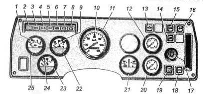
Rice. 5.10. Dashboard car GAZ-3307
1 - signaling device (red) for an emergency drop in oil pressure and clogging of the oil filter. Works at oil pressure from 40 to 80 kPa (from 0,4 to 0,8 kgf / cm 2).
2 - button for checking the status of the block of control lamps. When the button is pressed, the lamps of signaling devices 6, 7 and 8 of the block light up, if they are working.
3 - signaling device (green) for turning on the direction indicators of the trailer (flashing signal).
4 - signaling device (green) for turning on the direction indicators of the car (flashing signal).
5 - signaling device (green) for turning on side lights.
6.7 - Backup signaling devices.
8 - signaling device (red) for an emergency drop in the level of the brake fluid and the activation of the parking brake. With the ignition on, it lights up when the brake fluid level in the master cylinder reservoir is below the "MIN" mark or when the night brake is applied.
9 - signaling device (red) for overheating of the engine coolant. Illuminates when the coolant temperature is above 105***C.
10 - signaling device (blue) for switching on the main beam of the headlights.
11 - speedometer with a counter of the total mileage of the car.
12 - pressure gauge for controlling air pressure in the front brake circuit.
13 - signaling device for diagnostics of the engine management system.
14 - rear fog light switch.
15 - heater fan low speed switch. When the switch is in the on position, the lamp (green light filter) lights up.
16 - switch for the maximum speed of the heater fans. When the switch is in the on position, the lamp (green light filter) lights up. The electric motors operate at maximum speed when the switches 13 m 15 are turned on at the same time. When only one switch 15 is turned on, the electric motors do not work.
17 - central light switch.
The switch has three fixed positions:
I - side lights and license plate lights are on;
II - side lights, license plate lighting, dipped or main beam are on. Turning the central light switch knob clockwise adjusts the light intensity of the appliance.
18 - ABS diagnostic switch.
19 - ABS malfunction indicator.
20 - pressure gauge for controlling air pressure in the rear brake circuit.
22 - coolant temperature gauge.
23 - fuel gauge.
24 - indicator (orange) of the minimum amount of fuel in the tank. It is fixed when the remaining fuel in the tank is less than 12 liters.
25 - engine oil pressure gauge.
The location of the devices of the car GAZ-3309
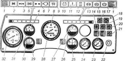
1 - buttons for checking the status of the lamps of the left and right blocks of control lamps. When button 1 is pressed, the lamps of the right or left blocks are turned on, if they are in good condition, except for the lamp pos. 9, which is checked when the instruments are turned on (instrument key position I, starter and anti-theft device).
2 and 11 - backup signaling devices.
3 - signaling device (green) for turning on the direction indicators of the trailer (flashing signal).
4 - signaling device (red) for overheating of the coolant. Illuminates when the coolant temperature is above 105°C.
5 - signaling device (green) for turning on side lights. It lights up when the headlights are turned on.
6 - signaling device (green) for turning on the direction indicators of the car (flashing signal).
7 - signaling device for diagnostics of the engine management system.
8 - signaling device (blue) to turn on the high beam.
9 - glow plug signaling device (orange.
10 - signaling device (orange) of a generator malfunction. Illuminates when the alternator is faulty.
12 - air filter clogging indicator (red). Lights up when the vacuum in the inlet pipe of the inlet pipe reaches 6,35 kPa (650 mm below the column).
13 - Fault indicator ABC.
14 - rear fog light switch.
15 - signaling device (red) for turning on the parking brake.
16 - heater fan low speed switch.
17 - signaling device (red) for an emergency drop in the fluid level in the brake system reservoir (flashing signal). When the gauges are on, it lights up when the brake fluid level in the master cylinder reservoir is below the MIN mark.
18 - switch for the maximum speed of the heater fans. The electric motors operate at maximum speed when switches 16 and 18 are turned on simultaneously. When only one switch 18 is turned on, the electric motors do not work.
19 pin glow plug control switch.
20 - ABS diagnostic switch.
21 - engine diagnostic request switch.
22 - central light switch (see Fig. 5.11).
23 - pressure gauge for controlling air pressure in the front brake circuit.
24 - pressure gauge for controlling air pressure in the rear brake circuit.
26 - fuel gauge.
27 - indicator (red) of the minimum amount of fuel in the tank. It is fixed when the remaining fuel in the tank is less than 12 liters.
28 - speedometer with total distance meter.
29 - engine oil pressure gauge.
30 - signaling device (red) for an emergency drop in oil pressure and clogging of the oil filter. Works at oil pressure from 40 to 80 kPa (from 0,4 to 0,8 kgf / cm 2).